Macurco
TM
Macurco RD-24 Manual
REV
–
1.0.0
[34-8708-4770-1]
18
|
P a g e
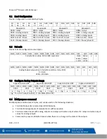
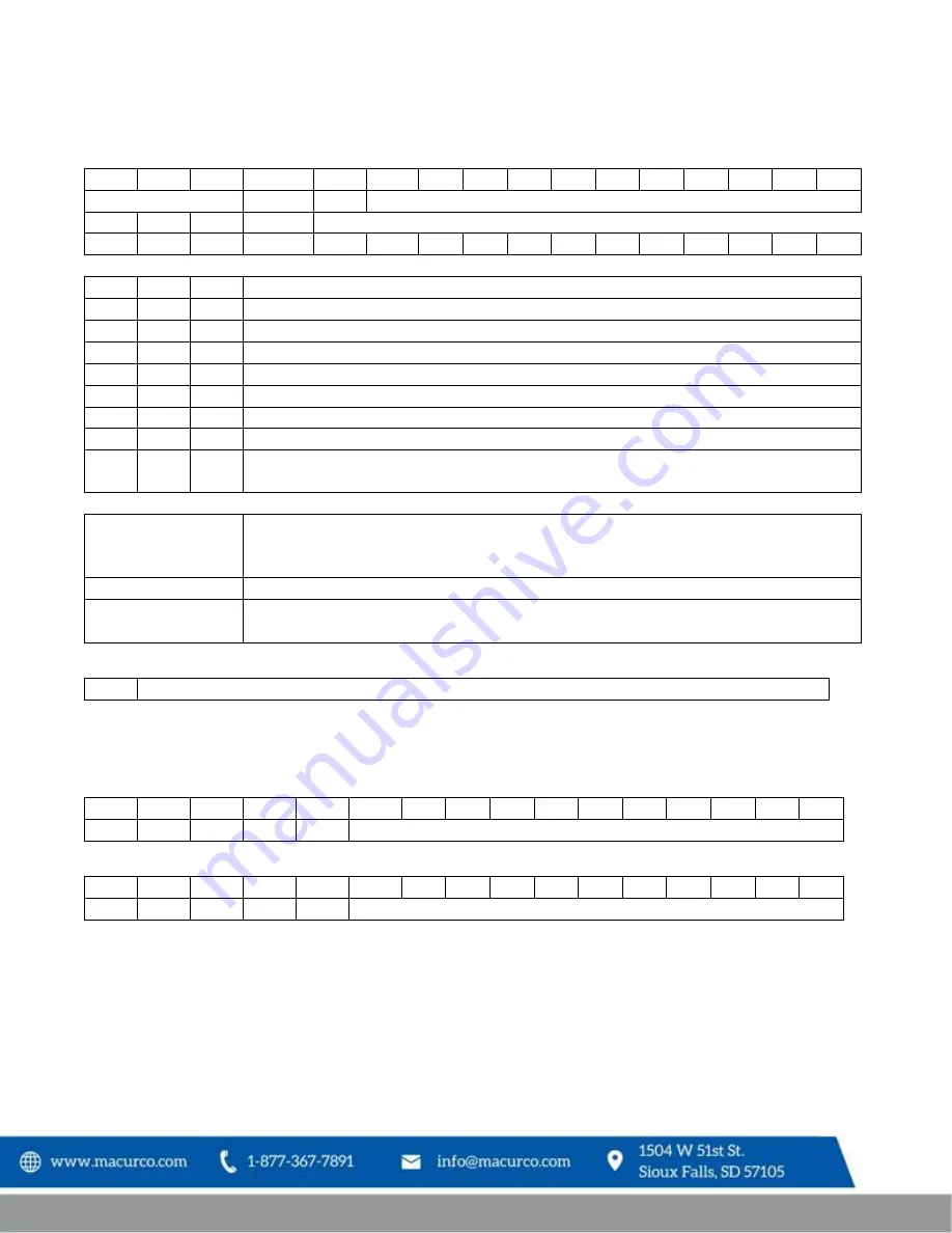
bit15 bit14 bit13
bit12
bit11 bit10 bit9 bit8 bit7 bit6 bit5 bit4 bit3 bit2 bit1 bit0
module#
device# relay
Analog value (mA x 100)
or
x
x
x
rly8 rly7 rly6 rly5 rly4 rly3 rly2 rly1
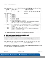
bit15 bit14 bit13
Description
0
0
0
Module #1
0
0
1
Module #2
0
1
0
Module #3
0
1
1
Module #4
1
0
0
Reserved
–
future use
1
0
1
Reserved
–
future use
1
1
0
Do not apply command. Dummy message
1
1
1
Apply to all 4 modules in the remote device, bit11 sets the state of the relays and
bits10-0 analog value to be used by DACs (Analog Outputs)
bit12
Each remote driver can have up to 4 modules connected. Each module has two relays
or two Analog outputs. Bit12 defines which output to be controlled 0
–
output1, 1-
output 2
bit11
Defines the state of relays, 0
–
OFF, and 1 - ON
bit10
Value to be written to the analog output (DAC). 0
–
2000. 0 = 0mA, 2000 = 20mA
Value to be written to relays. bits7-0.
NOTE:
Only “dummy message”
command has been implemented on this command.
6.5
Write Output Command Expansion Boards #1, #2, #3 and #4
Command to write to expansion board # has 4 bytes.
bit15 bit14 bit13 bit12 bit11 bit10 bit9 bit8 bit7 bit6 bit5 bit4 bit3 bit2 bit1 bit0
x
x
x
x
rly#1
Analog value#1 (0
–
2000)
bit15 bit14 bit13 bit12 bit11 bit10 bit9 bit8 bit7 bit6 bit5 bit4 bit3 bit2 bit1 bit0
x
x
x
x
rly#2
Analog value#2 (0
–
2000)
Note: If failsafe is active, then the remote relay must receive a message in a period equal to or less than the failsafe
timeout, otherwise relays will be placed in the failsafe position.


