background image

 
Macurco

TM

 Macurco RD-24 Manual 


REV 

 1.0.0 

[34-8708-4770-1] 

12 

|


P a g e


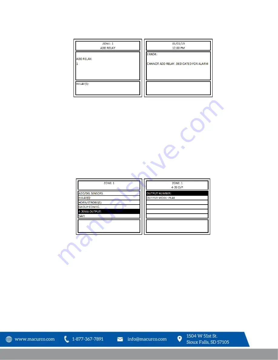
Figure 4-3 Zone Add Relay Error 

Figure 4-21 

 Zone Add Relay Error 

4.3.1.2


Configure 4-20mA OUTPUT or Analog Output 

Menu path: Main Menu-->CONFIGURE SYSTEM -->MANUAL CONFIGURE -->CONFIGURE ZONES -->ADD/EDIT ZONES--
>4-20MA OUTPUT: --> 

NOTE: Assigning Analog Output - The panel has 3 onboard analog outputs so remote analog inputs start at 4.  
Reference the Remote Device: I/O Chart at the end of this manual.   

To assign 4-20mA outpu

t to a zone, select “4

-

20MA OUTPUT:” from the zone configuration menu and press ENTER. 

Then select “OUTPUT NUMBER:” and press ENTER.


Figure 4-4 

 Zone 4-20mA Output Menu 

Input the 4-20mA output number to assign it to the zone. The display will return to the 4-20 O/P menu screen and 
show the currently assigned 4-20 mA output in the OUTPUT NUMBER field. 

NOTE: A zone can be assigned only one 4-20mA output, and a 4-20mA output can only be assigned to one zone. 4-
20mA output once assigned to a zone can be re-assigned to a different zone or can be deleted from the zone. 

Summary of Contents for RD-24

Page 1: ...IMPORTANT Keep these user instructions for reference Macurco RD 24 Modbus Remote Driver Installation Operation Manual...

Page 2: ...ion Connection 6 3 2 4 Input Output Connections 7 3 2 5 Expansion Board Connections 8 4 Operations 9 4 1 Power up 9 4 2 Initial Operating Mode 9 4 2 1 RD 24 Settings 9 4 2 2 Programming Mode 9 4 2 3 C...

Page 3: ...analog outputs or analog inputs Using Modbus communication you can control multiple I O based on the application The RD 24 requires 24VDC to operate and can be used to engage or disengage other equipm...

Page 4: ...mmunication Slots 1 4 Baud Rate 4800 9600 19200 default 98400 57600 115200 bps Enclosure NEMA 4X Warranty Two year limited warranty 3 Installation Instructions 3 1 Location Mounting Macurco RD 24 is s...

Page 5: ...button of the connector use flat headed screwdriver insert bare wire into respective wire cavity of the connector and release the white button Ensure that the wire cannot be easily pulled from the co...

Page 6: ...e twisted pair providing a pair for signal A B common COM and shield ground SHD connection NOTE Running the RS 485 cable adjacent to or in the same conduit with high voltage wires is not recommended a...

Page 7: ...7 P a g e 3 2 4 Input Output Connections Figure 3 4 RD 24 Board Diagram Macurco RD 24 Dip Switch EOL Resistor RS 485 COMMS IN OUT POWER IN OUT Expansion Board 2 SHD COM B A SHD COM B A GND GND 24V 24...

Page 8: ...ted 55mA Figure 3 5 Relay Expansion Board 3 2 5 2 Expansion Analog Output Board Expansion Analog Input Board 2 Analog Outputs Both outputs at 4mA Current 32mA Both at 20mA Current 70mA Figure 3 6 Anal...

Page 9: ...D 24 4 2 2 Programming Mode When the RD 24 is powered with address set to 254 it enters programming mode The STATUS LED will be flashing RED and GREEN alternatively every 200 milliseconds to indicate...

Page 10: ...the dip switch address to 255 and power on the RD 24 for at least 3 seconds The LED below the dip switch should blink green rapidly After at least 3 seconds power off the RD 24 Using the dip switch ch...

Page 11: ...lect DELETE RELAY from the RELAYS menu and press ENTER Input the relay number to delete and press ENTER to delete all relays assigned to the zone input 0 and press ENTER The relay s will be deleted fr...

Page 12: ...I O Chart at the end of this manual To assign 4 20mA output to a zone select 4 20MA OUTPUT from the zone configuration menu and press ENTER Then select OUTPUT NUMBER and press ENTER Figure 4 4 Zone 4...

Page 13: ...and NO2 sensor reading is 10 0ppm which corresponds to 12mA then the 4 20mA or Analog output assigned to the zone will output 12mA SCALE In this mode the 4 20mA value for all detectors added to a zon...

Page 14: ...that can be connected to the controller The sensor mapping will be done from top to bottom It grows from sensor 192 all the way to 128 By default DVP 1200 allocates space to connect to 192 digital se...

Page 15: ...ement 6 Figure 3 4 RD 24 Board Diagram 7 Figure 3 5 Relay Expansion Board 8 Figure 3 6 Analog Output Expansion Board 8 Figure 3 7 Analog Input Expansion Board 8 Table 4 1 Baud Rate Configuration 9 Tab...

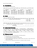
Page 16: ...00 00 00 00 00 00 00 00 00 85 4D 0x03 2 2 8 Vendor url Returns vendor url in C 01 03 00 15 00 08 55 ASCII C8 www macurco com R 01 03 10 77 77 77 2E 6D 61 63 75 72 63 6F 2E 63 6F 6D 00 A2 D6 0x03 3 0...

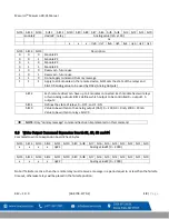
Page 17: ...to 3600 seconds state 0 OFF 1 ON Active 0 NO 1 YES x x bit15 bit14 bit13 bit12 bit11 bit10 bit9 bit8 bit7 bit6 bit5 bit4 bit3 bit2 bit1 bit0 Analog Output value when in fail safe condition mA x 100 0...

Page 18: ...elays or two Analog outputs Bit12 defines which output to be controlled 0 output1 1 output 2 bit11 Defines the state of relays 0 OFF and 1 ON bit10 Value to be written to the analog output DAC 0 2000...

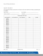
Page 19: ...Number _______________________________ Location of Install _________________________ Installed by _________________________________ Remote Device I O Chart Relay connection Connected device Zone Conf...

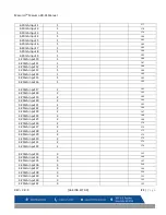
Page 20: ...4 20mA output 13 4 20mA output 14 4 20mA output 15 4 20mA output 16 4 20mA output 17 4 20mA output 18 4 20mA output 19 4 20mA output 20 4 20mA output 21 4 20mA output 22 4 20mA output 23 4 20mA outpu...

Page 21: ...5 1 191 4 20mA input 16 1 192 4 20mA input 17 2 161 4 20mA input 18 2 162 4 20mA input 19 2 163 4 20mA input 20 2 164 4 20mA input 21 2 165 4 20mA input 22 2 166 4 20mA input 23 2 167 4 20mA input 24...

Page 22: ...47 3 159 4 20mA input 48 3 160 4 20mA input 49 4 129 4 20mA input 50 4 130 4 20mA input 51 4 131 4 20mA input 52 4 132 4 20mA input 53 4 133 4 20mA input 54 4 134 4 20mA input 55 4 135 4 20mA input 5...

Page 23: ...ES OF MERCHANTABILITY AND FITNESS FOR PARTICULAR PURPOSE ARE LIMITED TO A PERIOD OF TWO 2 YEARS FROM THE PURCHASE DATE Macurco shall not be liable for any incidental or consequential damages for breac...

Reviews: