MN3205 / BL3208B / v3205 Power supplies
The power requirements for the MN3205, BL3208 and v3205 are slightly different. The MN3205 and v3205 are usually run at about 8.2v whereas the BL3208 can
run up to 10v. I recommend using a 9v power supply for these devices. For the MN3205 and v3205, use an 8.2v Zener for D2. This will limit the BBD power (VD) to
about 8v or so. For the BL3208, omit D2. D2 should also be omitted for the MN3005 and MN3008.
Clocks
MN3101 - This clock can be used with the MN3005, MN3008 and v3205 (not recommended). It allows you to run the ABDX at 15v with the MN3005 and MN3008.
While you can use it with the v3205, there is no advantage to it since you must run the ABDX at 9v in this case.
NOTE: if you are using the MN3101 with the
v3205, you must use D3 to approximate the correct Vgg voltage for pin8 of the clock (14/15 of Vdd). In all other cases (including when using an
MN3102, BL3102 or v3102) you should omit D3.
The 3102 clocks automatically generate the correct Vgg voltage needed in each case.
MN3102, BL3102, v3102 – Any of these should work with the MN3008, BL3208 and v3205.
I do recommend using the one that matches the device you are using
.
IOW, with the MN3008, use the MN3102 (remember you cannot run the ADBX at 15v with this option), the BL3208B uses the BL3102 and the v3205 uses the
v3102.
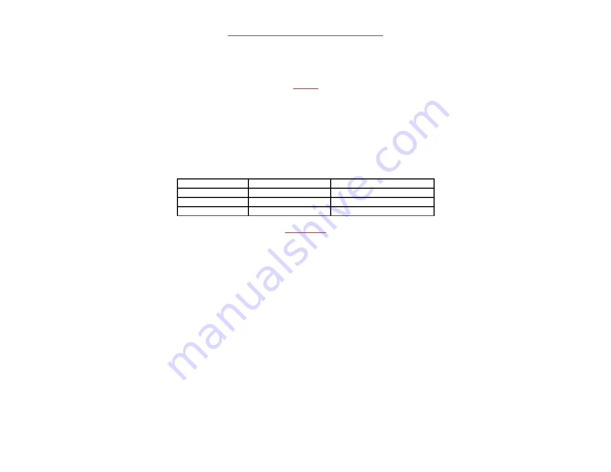
BBD
Recommended Clock
Recommended Compander
MN3005, MN3008
MN3101
NE570, SA571
BL3208B
BL3102
NE570, SA571
V3205
V3102
NE570, SA571, v571
Modulation
The modulation section is a tweaked version of the Mod board for the original Aquaboy project. It uses an LFO to generate either triangle or square wave
modulation which drives an LED/LDR combo. The LDR combines with the Depth pot to create a variable resistance to ground from lug 1 of the Delay control. As
the LED brightness fluctuates, the resistance on the photocell goes up and down which creates an oscillating change on the overall delay time. This can go up to
fairly extreme settings.
To tweak the overall range/intensity of the LFO further, you can use a large resistor (R56) in parallel with the LDR/Depth control
.
You should socket this component and try different values ranging from 220k – 1M5 for experimentation. 470k is a good starting point.
Because of the R56 mod, a variety of LED/LDR combinations can be used. A VTL5C3 is pretty standard for this type of modulation control, but is also quite
expensive. If you want to make your own vactrol, a photocell ranging from 1M to 5M dark resistance should work fine. The LED can be a 3mm or 5mm red
diffused. You should shield the LED/LDR combo with some heat shrink or at least block external light from it when testing your build.
When building the
15v/MN3005 version of the ABDX, use 8k2 resistors for R50 and R51. This will help reduce the added brightness of the vactrol’s internal LED due to the higher
voltage supply.
D4 is meant to be an external indicator of the rate of the LFO and should be mounted to the enclosure like any LED indicator. It is optional and not necessary to
the function of the modulation.
2019 Note: If you run the ABDX at 15v for the MN3005 configuration, changing R43 and R44 to either 220k or 470k will increase the overall depth of modulation.
Summary of Contents for ABDX
Page 4: ......


