12
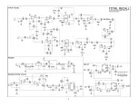
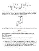
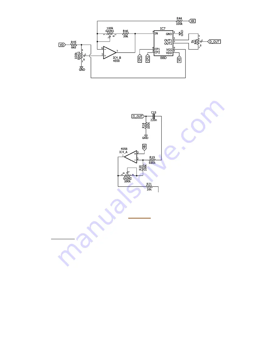
The gain recovery stage starts at XR. It is fed through an inverted gain stage with a trimmer to adjust the output volume.
Here the biasing is done differently with the bias voltage applied to the non-inverted input of the op-amp. At the outputs,
we have a new trimmer, BAL. This trimmer is used to align the two output waveforms for cleanest delay signal obtainable.
After the BAL trimmer the signal gets sent to the second and final gain recovery stage.
After the second gain recovery stage, the signal is sent through additional filters, the expandor, then mixed to the output of
the circuit (not shown).
Procedure
Tools required: audio source, audio probe.
Before you start, remove IC7 if you have it installed. We will bias one BBD at a time. Set your controls as follows:
DELAY - full up
FDBK - a little less than halfway up
MOD - all the way down
LEVEL - about 1/3rd up
BLEND - doesn't matter (you should leave the circuit output disconnected since we will be audio probing)
CH/VB switch - doesn't matter
Leave all the trimmers in their halfway position to start.
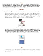
Connect the TR PCB to your power supply. Use an audio source at the input of the circuit (J1). While you can just
strum your guitar it might be difficult to make trimmer adjustments at the same time. If you have a looper, record a
few single notes a few seconds apart and feed that into the circuit. Or, improvise with something else.
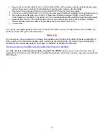
Connect your audio probe to either pin3 or pin4 of IC6. Now adjust BIAS1 until you hear delay output. Adjust
BIAS1 further until you find the min and max settings where you have clean delay output. Set BIAS1 to
approximately the middle point of this range. Now make very small adjustments left and right until you find the
spot where the delay output is cleanest and strongest.
Summary of Contents for Total Recall
Page 2: ...2 ...
Page 5: ...5 ...
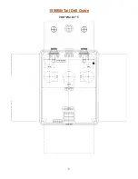
Page 6: ...6 1590BB Tall Drill Guide 7 08 W x 8 1 T ...
Page 15: ...15 ...


