Build Notes
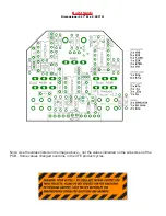
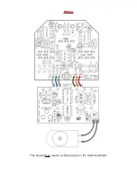
As recommended on pg.4, jumper the two spots for the 100R resistors like so:
Voltages
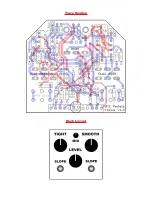
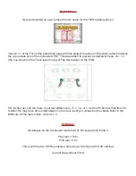
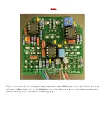
Version 1.1 of the Focus (the board that ships with this project) requires a 1M resistor soldered across
the two outside pins of the right-side DPDT. This was added to prevent a small switch pop. Ver. 1.3
(the one shown on the Trace layout on pg.2) has this resistor on the PCB.
PS: Insofar as I can tell, there is not real difference in v1.1, 1.2, or 1.3 of the PCB other than this 1M
resistor. He may have done small tweaks on the trace routing or values but the values listed in the
BOM are for the last version, which is 1.3.
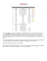
All voltages on the ICs should read about 0v DC except pins 8 and 4.
Pin8 (all): +7.86v
Pin4 (all): -6.8v
This is with the two 100Rs jumpered and using a One Spot with 9.42 nominal.
Current Draw: About 57mA


