background image

IT

EN

FR

ES

15

Madas Technical Manual

 - 5|5.1a - REV. 0 of 5

th

 Apr 2019

FRG-RG/2MCC - FRG-RG/2MCS

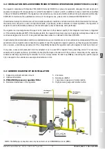
5.2 - Adjusting the outlet pressure (Pa)

The outlet pressure Pa (unless specifically requested) is factory-set with the regulator installed as indicated in 3.4 and with the 

adjustment screw (

2

) set approximately at the minimum setting value. The relief valve is set accordingly. 

If the regulator is installed in different positions, check and reset the outlet pressure Pa, and consequently the devices 

incorporated in the regulator;
Adjust the outlet pressure as follows:
• Unscrew the cap (

1

);

• Unscrew the adjustment screw (

2

) and set it to the minimum setting allowed (threaded end of the top cover (

3

));

• Start the system or make sure there is a minimum flow downstream of the regulator;
• To increase the pressure calibration downstream of the regulator, tighten the adjustment screw (

2

) to the desired value. 

Perform the reading with a calibrated pressure gauge, installed downstream of the regulator to at least 5 DN (see example 

in 3.4);

• Screw the cap (

1

) back on and if necessary, seal it in that position using the appropriate seal holes (if any);

• Use pressure outlets (

15

) on the device only for zero flow or very low flow measurements. 

  6.0 - RECOMMENDED PERIODIC CHECKS

• Use a suitable calibrated tool to ensure the bolts are tightened as indicated in 3.2;

• Check the tightness of the flanged/threaded connections on the system;

• Check the tightness and operation of the regulator/relief valve;

The final user or installer is responsible for defining the frequency of these checks based on the severity of the service conditions.

6.1 - CHECK THAT THE RELIEF VALVE IS WORKING PROPERLY

• Start the system as described in point 4.0;

• Slowly close the valve downstream of the regulator;

• Loosen and remove the cap (

1

);

• Use an 8 mm socket spanner to press the adjustment nut (

20

) to increase the pressure Pa above the preset value. Use a 

calibrated pressure gauge for the reading;

• Remove the socket spanner. The generated overpressure will be discharged outwards and the Pa will begin to decrease to 

the relief valve setting value. Relief valve operation is verified;

• Close the cap (

1

);

• Open the relief valve to discharge the created overpressure; 

• Close the relief valve (the regulator goes to the closing pressure) and open the ball valve downstream of the regulator.


 7.0 - MAINTENANCE

• No maintenance operations need to be carried out inside the device. If operations must be carried out inside the 

device (changing the spring, replacing the filter, etc.), it is advisable to contact the Technical Department. In any 
case, before carrying out any dismantling operation on the device, make sure that there is no pressurised gas inside. 

8.0 - TRANSPORT, STORAGE AND DISPOSAL

•  During transport the material needs to be handled with care, avoiding any impact or vibrations to the device;
•  If the product has any surface treatments (ex. painting, cataphoresis, etc) it must not be damaged during transport;
•  The transport and storage temperatures must observe the values provided on the rating plate;
•  If the device is not installed immediately after delivery it must be correctly placed in storage in a dry and clean place;
•  In humid facilities, it is necessary to use driers or heating to avoid condensation;
•  At the end of its service life, the product must be disposed of in compliance with the legislation in force in the country where 

this operation is performed.

Summary of Contents for FRG/2MCC

Page 1: ...ating pressure range Plage de pression de fonctionnement Rango de la presi n de funcionamiento Pe 0 5 3 bar 0 5 5 bar Attacchi filettati Threaded connections Raccords filet s Conexiones roscadas DN 15...

Page 2: ...gulateurs tableau 1 Caudal de los reguladores tabla 1 Disegni Drawings Dessins Dise os 32 Dimensioni tabella 2 39 Dimensions table 2 Dimensions tableau 2 Dimensiones tabla 2 Caratteristiche molle di...

Page 3: ...tore Tale scarico convogliabile all esterno nel caso di installazioni in ambienti con scarsa ventilazione Possono essere forniti anche senza valvola di sfioro presa di pressione in uscita 1 2 LEGENDA...

Page 4: ...e compact fino a 25 m3 h RG 2MCC Regolatore di pressione senza filtro Versione compact fino a 25 m3 h FRG 2MCS Regolatore di pressione con filtro Versione standard RG 2MCS Regolatore di pressione senz...

Page 5: ...erondelleperevitaredanneggiamenti alle flange in fase di serraggio Durante la fase di serraggio prestare attenzione a non pizzicare o danneggiare la guarnizione Serrare i dadi o bulloni gradualmente s...

Page 6: ...caso di intervento della valvola di sfioro integrata o in caso di rottura della membrana di funzionamento 17 In caso di rottura membrana il regolatore costituisce una sorgente di emissione di atmosfe...

Page 7: ...inetto di sfiato Controllare la tenuta di tutte la guarnizioni dell impianto e verificare la tenuta interna esterna del regolatore Aprire molto lentamente la valvola di intercettazione di valle Verifi...

Page 8: ...6 1 VERIFICA DEL FUNZIONAMENTO DELLO SFIORO Avviare l impianto come indicato al punto 4 0 Chiudere lentamente il rubinetto a valle del regolatore Svitare e rimuovere il tappo 1 Premendo con chiave a...

Page 9: ...one ammissibile Pe Pressione massima o range di pressione di ingresso alla quale garantito il funzionamento del prodotto 20 60 C Range di temperatura alla quale garantito il funzionamento del prodotto...

Page 10: ...erpressure occurs downstream of the regulator This discharge can be conveyed outwards if the installation is in a poorly ventilated environment They can also be supplied without the relief valve outle...

Page 11: ...CC Pressure regulator with filter Compact version up to 25 m3 h RG 2MCC Pressure regulator without filter Compact version up to 25 m3 h FRG 2MCS Pressure regulator with filter Standard version RG 2MCS...

Page 12: ...relative washers inside the bolts in order to prevent damage to the flanges during tightening When tightening be careful not to pinch or damage the gasket Tighten the nuts or bolts gradually in a cros...

Page 13: ...can be dangerous with respect to the presence of other devices nearby if the integrated relief valve is triggered or if the working diaphragm 17 If the diaphragm fails the regulator becomes a source...

Page 14: ...he internal external tightness of the regulator Open the downstream shut off valve very slowly Check the operation of the regulator 5 0 CALIBRATION Before carrying out the operations make sure that th...

Page 15: ...ns 6 1 CHECK THAT THE RELIEF VALVE IS WORKING PROPERLY Start the system as described in point 4 0 Slowly close the valve downstream of the regulator Loosen and remove the cap 1 Use an 8 mm socket span...

Page 16: ...lowable pressure Pe Maximum pressure or inlet pressure range that product operation is guaranteed at 20 60 C Temperature range within which product operation is guaranteed Pa Outlet pressure range CE...

Page 17: ...lateur sont constat es Ce d chargement peut tre envoy vers l ext rieur en pr sence d installations dans des environnements ayant une mauvaise ventilation Ils peuvent aussi tre fournis sans vanne d vac...

Page 18: ...vec filtre Version compacte jusqu 25 m3 h RG 2MCC R gulateur de pression sans filtre Version compacte jusqu 25 m3 h FRG 2MCS R gulateur de pression avec filtre Version standard RG 2MCS R gulateur de p...

Page 19: ...endommager les brides pendant le serrage Pendant la phase de serrage veiller ne pas pincer ni endommager le joint Serrer les crous ou les boulons progressivement selon un sch ma en croix voir l exemp...

Page 20: ...ppareils en cas d intervention de la vanne d vacuation int gr e ou en cas de rupture de la membrane de fonctionnement 17 En cas de rupture de la membrane le r gulateur constitue une source d mission d...

Page 21: ...de tous les joints de l installation et v rifier l tanch it interne externe du r gulateur Ouvrir tr s lentement la vanne d arr t en aval V rifier le fonctionnement du r gulateur 5 0 TALONNAGE Avant d...

Page 22: ...tions de fonctionnement 6 1 V RIFICATION DU FONCTIONNEMENT DE L VACUATION D marrer l installation et armer comme indiqu au point 4 0 Fermer lentement le robinet en aval du r gulateur D visser et ter l...

Page 23: ...de connexion PS Pression admissible Pe Pression maximum ou plage de pression d entr e laquelle le fonctionnement du produit est garanti 20 60 C Plage de temp rature laquelle le fonctionnement du produ...

Page 24: ...caudales de gas si hay sobrepresiones despu s del regulador Esta descarga se puede transportar al exterior en instalaciones en ambientes con poca ventilaci n Tambi n pueden suministrarse sin v lvula d...

Page 25: ...act hasta 25 m3 h RG 2MCC Regulador de presi n sin filtro Versi n compact hasta 25 m3 h FRG 2MCS Regulador de presi n con filtro Versi n est ndar RG 2MCS Regulador de presi n sin filtro Versi n est nd...

Page 26: ...s para evitar da os a las bridas en fase de apriete Durante la fase de apriete aseg rese de no pellizcar ni da ar la junta Apriete las tuercas o pernos gradualmente seg n un esquema de cruz v ase el e...

Page 27: ...v lvula de alivio integrada o en caso de rotura de la membrana de funcionamiento 17 En caso de rotura de membrana el regulador constituye una fuente de emisi n de atm sfera explosiva constantemente y...

Page 28: ...juntas de la instalaci n y compruebe la estanqueidad interna externa del regulador Abra muy lentamente la v lvula de interceptaci n posterior Compruebe el funcionamiento del regulador 5 0 CALIBRACI N...

Page 29: ...e las condiciones de servicio 6 1 COMPROBACI N DEL FUNCIONAMIENTO DEL ALIVIO Ponga en marcha la instalaci n tal como se indica en el punto 4 0 Cierre lentamente el grifo de la parte posterior del regu...

Page 30: ...i metro de conexi n PS Presi n admisible Pe Presi n m xima o rango de presi n de entrada en la que se garantiza el funcionamiento del producto 20 60 C Intervalo de temperatura en el que se garantiza e...

Page 31: ...85 300 70 100 100 100 100 350 40 75 90 90 90 400 40 90 100 100 100 2MCS STANDARD DN 20 20 42 42 50 50 50 30 50 50 55 55 55 50 70 70 70 70 70 100 100 100 100 100 100 200 80 100 100 100 100 300 80 100...

Page 32: ...1 COMPACT FRG 2MCC RG 2MCC Q max 25 m3 h 8mm Per taratura Pa For Pa setting Pour talonnage Pa Para calibraci n Pa Parte superiore regolatore dotato di sfioro Top part of the regulator with relief val...

Page 33: ...pour r gler Pa Herramienta requerida para calibraci n de Pa Pa Range mbar con sfioro with relief avec vacuation con alivio senza sfioro without relief sans vacuation sin alivio 10 25 13mm 25 35 35 80...

Page 34: ...RG 2MCS RG 2MCS Q max 100 m3 h 8mm Per taratura sfioro For relief valve setting Pour talonnage vacuation Para calibraci n alivio Parte superiore regolatore dotato di sfioro Top part of the regulator w...

Page 35: ...our r gler Pa Herramienta requerida para calibraci n de Pa Pa Range mbar con sfioro with relief avec vacuation con alivio senza sfioro without relief sans vacuation sin alivio 10 25 13mm 20 30 30 60 6...

Page 36: ...eriore regolatore con o senza sfioro Top part of the regulator with or without relief valve Partie sup rieure r gulateur avec ou sans vacuation Parte superior del regulador con y sin alivio RG FRG 2MC...

Page 37: ...ngia solo su versioni 2MCS 17 Membrana di funzionamento 18 Tappo antipolvere 19 Molla di taratura sfioro 20 Regolazione sfioro 21 Tappo G 1 8 presa impulso esterna solo su 2MCS IT EN fig 1 2 and 3 1 C...

Page 38: ...nt 18 Bouchon anti poussi re 19 Ressort d talonnage vacuation 20 R glage vacuation 21 Bouchon G 1 8 prise impulsion externe uniquement sur 2MCS fig 1 2 y 3 1 Tap n de cierre 2 Tornillo de regulaci n P...

Page 39: ...ons 2MCS avec Pa 200 mbar B 194 E 154 5 En 2MCS con Pa versiones de 200 mbar B 194 E 154 5 Attacchi flangiati Flanged connections Raccords bride Conexiones embridadas Versioni compact 2MCC Compact ver...

Page 40: ...0410 1 5x29x58x7 30 60 MO 0430 2x29x49x7 60 90 MO 0460 2x29x66x7 90 170 MO 0520 2 5x29x50x7 110 180 MO 0540 2 5x29x60x7 75 170 400 MO 1320 3 5x29 8x64x9 300 650 MO 1305 3 5x29 8x98x11 5 600 900 MO 25...

Page 41: ...denoting the connection to get the sealing washer compensation diaphragm and working diaphragm in FKM Ajouter la lettre V apr s la lettre indiquant les connexions pour obtenir rondelle de tenue et mem...

Page 42: ...Modello Compact con filtro Compact model with filter Mod le Compact avec filtre Modelo Compact con filtro DN 25 Pe 0 5 5 bar 35 80 mbar senza OPSO without OPSO sans OPSO sin OPSO senza UPSO without U...

Page 43: ...hange Not all combinations are possible they must be functionally compatible It is advisable to contact our sales department for confirmation of feasibility Le tableau reporte quelques exemples pour i...

Page 44: ...XX3 FCC030000 5XX3 RCC03 5XX3 RCC030000 5XX3 DN 25 1 10 25 1 5 12 FCC04 1XX1 FCC040000 1XX1 RCC04 1XX1 RCC040000 1XX1 1 10 25 2 10 60 FCC04 1XX2 FCC040000 1XX2 RCC04 1XX2 RCC040000 1XX2 2 25 35 2 10 6...

Page 45: ...le per la conferma della fattibilit Table shows some examples to illustrate how you can combine the setting springs For compact 2MCS models versions with Pe 0 5 to 3 bar or Pe 0 5 to 5 bar code 0000 O...

Page 46: ...000 2XX1 2 20 30 2 10 60 FCS03 2XX2 FCS030000 2XX2 RCS03 2XX2 RCS030000 2XX2 3 30 60 2 10 60 FCS03 3XX2 FCS030000 3XX2 RCS03 3XX2 RCS030000 3XX2 4 60 90 2 10 60 FCS03 4XX2 FCS030000 4XX2 RCS03 4XX2 RC...

Page 47: ...S040000 7XX4 RCS04 7XX4 RCS040000 7XX4 8 300 650 4 40 200 FCS04 8XX4 FCS040000 8XX4 RCS04 8XX4 RCS040000 8XX4 9 600 1500 4 40 200 FCS04 9XX4 FCS040000 9XX4 RCS04 9XX4 RCS040000 9XX4 versioni con membr...

Page 48: ...ons le droit de toute modification technique et constructive Nos reservamos el derecho de realizar cualquier cambio t cnico y estructural Sede legale Via V Moratello 5 6 7 37045 Z A I Legnago VR Italy...

Reviews: