ES
FR
EN
IT
14
Madas Technical Manual
- 5|5.1a - REV. 0 of 5
th
Apr 2019
FRG-RG/2MCC - FRG-RG/2MCS
4.0 - FIRST START-UP
Before commissioning, verify that:
• all of the instructions on the rating plate, including the direction of flow, are observed;
• the hole of the dust cap (
18
) is not clogged;
• IMPORTANT:
The leak test of the piping must be performed without subjecting the diaphragm of the regulator
(therefore, the downstream pipe section) to a pressure higher than 300 mbar (for reinforced diaphragm 1.5 times
the regulator setting pressure). Use special manual gas closing devices to avoid damaging the regulator;
• The pressurisation manoeuvre of the equipment must be carried out very slowly so as to avoid possible damage.
NOTE:
under no circumstances should a blind cap be placed instead of the dust cap (
18
) as the regulator may
not work;
• Open the downstream vent valve partially;
• Slowly open the upstream shut-off devices (e.g. solenoid valves, OPSO shut-off valve, etc.);
• Wait until the downstream pressure stabilises at the calibration value Pa of the spring (indicated on the rating plate);
• Close the vent valve;
• Check the tightness of all the system gaskets and check the internal/external tightness of the regulator;
• Open the downstream shut-off valve very slowly;
• Check the operation of the regulator.
5.0 - CALIBRATION
Before carrying out the operations, make sure that the supplied spring/s is/are suitable for the desired Pa and differential
relief valve fields.
5.1 - Adjusting the relief valve (differential DfRv)
NOTE
: The relief valve (if any) in these regulators is differential, therefore the range value (DfRv) indicated must be added to
the range value of the outlet pressure (Pa).
Example: Pa=20
-
30 mbar - DfRv=10
-
60 mbar.
Means that the relief valve can be calibrated from: (Pa min + DfRv min) = 20+10=30 mbar to: (Pa max + DfRv max) =
30+60=90 mbar
Therefore the effective range of the relief valve (in this case) is 30
-
90 mbar.
• Start the system and set the shut off as described in point 4.0;
• Slowly close the valve downstream of the regulator;
• Loosen and remove the cap (
1
);
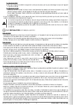
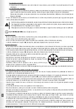
• Use the 8 mm socket spanner (see fig. 1 and 2) to fully tighten the nut (
20
);
• Use the 8 mm socket spanner to press the adjustment nut (
20
) and increase the pressure Pa, reading it on the pressure
gauge, up to the desired setting value;
• Without pressing further, slowly loosen the adjustment nut (
20
) until the pressure Pa begins to decrease, shown on the
pressure gauge;
• In this case, the relief valve is set to the desired value;
• Remove the socket spanner and close the cap (
1
).

