background image

13

IT

EN

FR

ES

M16/RM N.C. EEX

Madas Technical Manual

 - 2|2.2b - REV. 0 of 10

th

 May 2018

1

2

3

4

5

6

7

8

9

piping

application

discharge in 

open air

internal thermal unit

ZONE 1

external roof

10

discharge in 

open air

discharge in 

open air

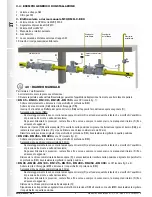
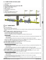
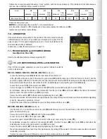
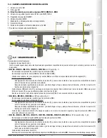
3.4 - GENERIC EXAMPLE OF INSTALLATION

1.  SM jerk ON/OFF valve 

2.  FM gas filter

3.  M16/RM N.C. Manual reset solenoid valve EEX

4.  OPSO series MVB/1 MAX shut off valve

5.  RG/2MC pressure regulator

6.  MVS/1 relief valve

7.  Pressure gauge and relative button

8.  Gas detector

9.  SM remote jerk ON/OFF valve lever control

10. Compensation/Vibration damping joint


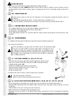
4.0 - MANUAL RESET

To reset the solenoid valve:
• Make sure the power supply is connected;
• Close the flow downstream of the solenoid valve in order to balance the pressure between upstream and downstream when 

opening.

• DN 65 - DN 80 - DN 100 - DN 125 - DN 150

 without CPI (see fig. 1):

• Loosen completely and remove the protective cover (

13

);

• Loosen the reset pin (

14

) from the fastening screw (

15

);

• Insert the non-threaded part of the reset pin (

14

) in the hole provided on the hex knob (

1

); 

• Using the pin (

14

):

• Turn the reset knob (

1

) slightly clockwise and wait a few seconds for the pressure upstream and downstream of the 

valve to stabilise;   

• After balancing the pressure, turn the reset knob (

1

) clockwise to its stroke end, when it is coupled;

• Remove the pin (

14

) from the knob (

1

) and screw it on in its original position. Alternatively to the reset pin (

14

), it is 

possible to use a size 32 commercial spanner to turn the reset knob (

1

);

• Screw the protective cover (

13

) back on in its original place. Or seal it in that position.

• DN 200 - DN 250 - DN 300

 without CPI (see fig. 2):

• Loosen completely and remove the protective cover (

13

);

• Using a size 32 commercial spanner: 

• Turn the reset knob (

1

) slightly clockwise and wait a few seconds for the pressure upstream and downstream of the 

valve to stabilise; 

• After balancing the pressure, turn the reset knob (

1

) clockwise to its stroke end, when it is coupled;

• Remove the commercial spanner from the knob (

1

), then tighten the protective cover (

13

) back into its original position. 

Or seal it in that position.

• DN 65 - DN 80 - DN 100 - DN 125 - DN 150 - DN 200 - DN 250 - DN 300

 with CPI (see fig. 3 and 4):

• Loosen the fastening screw (

23

) and remove the protective cover (

13

);

• Using a size 32 commercial spanner: 

• Turn the reset knob (

1

) slightly clockwise and wait a few seconds for the pressure upstream and downstream of the 

valve to stabilise; 

• After balancing the pressure, turn the reset knob (

1

) clockwise to its stroke end, when it is coupled;

• Remove the commercial spanner from the knob (

1

);

• Screw the protective cover (

13

) back on in its original place and secure it with the screw (

23

). Or seal the cover in that 

position.

Summary of Contents for M16/RM N.C. DN 65 EEX

Page 1: ...R E S Pressione massima di esercizio Maximum operating pressure Pression maximum de fonctionnement Presi n m xima de funcionamiento 0 5 6 bar Attacchi flangiati Flanged connections Raccords brides Con...

Page 2: ...i tabella 1 38 Dimensions table 1 Dimensions tableau 1 Dimensiones tabla 1 Bobine e connettori di ricambio tabella 2 39 Spare coils and connectors table 2 Bobines et connecteurs de rechange tableau 2...

Page 3: ...e Ulteriori informazioni riguardanti il CPI switch sono riportate in 7 0 Norme di riferimento EN 161 EN 13611 1 2 LEGENDA SIMBOLI ATTENZIONE Viene richiamata l attenzione su dettagli tecnici rivolti a...

Page 4: ...essere liberi da corpi estranei Verificare che le controflange di ingresso e uscita siano perfettamente coassiali e parallele per evitare di sottoporre il corpo a inutili sforzi meccanici calcolare in...

Page 5: ...esplosione approvate Es Scatola terminale con protezione e o sicurezza aumentata secondo EN 60079 7 Assicurarsi che i cavi di collegamento siano inseriti correttamente nel terminale elettrico avendo c...

Page 6: ...o 14 dalla manopola 1 e avvitarlo nella posizione originale In alternativa al perno di riarmo 14 per ruotare la manopola di riarmo 1 si pu utilizzare una chiave commerciale da 32 mm Riavvitare nella p...

Page 7: ...to che la bobina idonea anche per alimentazione permanente il riscaldamento della bobina in caso di servizio continuo un fenomeno del tutto normale E consigliabile evitare il contatto a mani nude con...

Page 8: ...inistra elanuovamanopola in dotazione al kit La manopola 1 dev essere inserita con il foro filettato rivolto verso l alto e facendo coincidere tale foro filettato col foro del perno Fissare la manopol...

Page 9: ...diritti di garanzia o risarcimento danni Sono esclusi inoltre dalla garanzia i lavori di manutenzione il montaggio di apparecchi di altri produttori la modifica del dispositivo e l usura naturale 10...

Page 10: ...CPI can also be installed at a later stage Further information regarding the CPI switch is available in 7 0 Reference standards EN 161 EN 13611 1 2 KEY OF SYMBOLS ATTENTION Attention is drawn to the t...

Page 11: ...caps if any must be removed prior to installation Valve pipes and insides must be clear of any foreign bodies Make sure the inlet and outlet counter flanges are perfectly coaxial and parallel in order...

Page 12: ...reased safety according to EN 60079 7 Make sure the connection cables are inserted correctly into the electrical terminal ensuring they are not crushed and or damaged in order to prevent short circuit...

Page 13: ...e reset knob 1 clockwise to its stroke end when it is coupled Remove the pin 14 from the knob 1 and screw it on in its original position Alternatively to the reset pin 14 it is possible to use a size...

Page 14: ...is not electrically powered Since the coil is also suitable to be permanently powered coil heating in case of continuous operation is an entirely normal phenomenon It is advisable to avoid touching t...

Page 15: ...nob supplied with the kit The knob 1 must be inserted with the threaded hole facing up and making said threaded hole match up with the pin hole Secure the knob 1 by tightening and securing the grub sc...

Page 16: ...ights of the warranty or compensation for damage The warranty also excludes maintenance work other manufacturers s assembling units making changes to the device and natural wear 10 0 RATING PLATE DATA...

Page 17: ...plus tard Plus d informations sur les commutateurs CPI sont donn es dans 7 0 Normes de r f rence EN 161 EN 13611 1 2 L GENDE SYMBOLES ATTENTION Nous attirons votre attention sur les d tails technique...

Page 18: ...nt rieurs de la vanne doivent tre libres de corps trangers V rifier que les contre brides d entr e et sortie soient parfaitement parall les pour viter de soumettre le corps des efforts m caniques inut...

Page 19: ...id flagrant agr Ex Bo te bornes avec protection et ou s curit accrue selon EN 60079 7 Assurez vous que les c bles de connexion sont correctement ins r s dans la borne lectrique en veillant ce qu ils n...

Page 20: ...erlagoupille 14 dubouton 1 etlavisserdanslapositiond origine Commealternative labrocheder initialisation 14 pour faire tourner le bouton de r initialisation 1 vous pouvez utiliser une cl commerciale d...

Page 21: ...u que la bobine est galement adapt e pour une alimentation permanente le r chauffement de la bobine en cas de service continu est un ph nom ne tout fait normal Il est conseill d viter tout contact mai...

Page 22: ...la gauche et le nouveau bouton fourni avec le kit Le bouton 1 doit tre ins r avec le trou filet vers le haut et en faisant correspondre le trou filet avec le trou de la goupille Fixez le bouton 1 en...

Page 23: ...un droit de garantie ou de d dommagement ne peut tre revendiqu Sont galement exclus de la garantie les travaux d entretien le montage d appareils d autres producteurs la modification du dispositif et...

Page 24: ...v lvula El CPI se puede instalar tambi n a posteriori M s informaci n relacionada con el interruptor CPI se encuentra en el punto 7 0 Normas de referencia EN 161 EN 13611 1 2 LEYENDA DE S MBOLOS ATEN...

Page 25: ...la instalaci n Las tuber as y partes interiores de la v lvula no deben tener cuerpos extra os Compruebe que las contrabridas de entrada y salida est n perfectamente coaxiales y paralelas para evitar...

Page 26: ...ados para protecci n contra explosi n Ej Caja terminal con protecci n e o seguridad aumentada seg n EN 60079 7 Aseg rese de que los cables de conexi n est n conectados correctamente en el terminal el...

Page 27: ...cha el bot n de rearme 1 hasta que se produzca el enganche Quite el perno 14 del bot n 1 y enr squelo en la posici n original Como alternativa al perno de rearme 14 para girar el bot n de rearme 1 se...

Page 28: ...el ctrica Como la bobina es id nea tambi n para alimentaci n permanente el calentamiento de la bobina en caso de funcionamiento continuo es un fen meno normal Se aconseja evitar el contacto de las man...

Page 29: ...erda y el bot n nuevo en equipamiento con el kit El bot n 1 debe introducirse con el orificio roscado dirigido hacia arriba y haciendo coincidir dicho orificio roscado con el orificio del perno Fije e...

Page 30: ...ant a ni resarcimiento de da os Adem s se excluyen de la garant a los trabajos de mantenimiento el montaje de aparatos de otros fabricantes la modificaci n del dispositivo y el desgaste natural 10 0 D...

Page 31: ...t CPI Dessins indicatifs pour M16 RM N C EEX DN 65 DN 80 DN 100 DN 125 DN 150 sans CPI Dise os orientativos para M16 RM N C EEX DN 65 DN 80 DN 100 DN 125 DN 150 sin CPI OPEN RIARMO MANUALE CON PERNO I...

Page 32: ...ns indicatifs pour M16 RM N C EEX DN 200 DN 250 DN 300 sans CPI Dise os orientativos para M16 RM N C EEX DN 200 DN 250 DN 300 sin CPI RIARMO MANUALE CON CHIAVE COMMERCIALE 32mm eseguire come indicato...

Page 33: ...fs pour M16 RM N C EEX DN 65 DN 80 DN 100 DN 125 DN 150 avec CPI Dise os orientativos para M16 RM N C EEX DN 65 DN 80 DN 100 DN 125 DN 150 con CPI RIARMO MANUALE CON CHIAVE COMMERCIALE 32mm eseguire c...

Page 34: ...N 200 DN 250 DN 300 avec CPI Dise os orientativos para M16 RM N C EEX DN 200 DN 250 DN 300 con CPI RIARMO MANUALE CON CHIAVE COMMERCIALE 32mm eseguire come indicato in 4 0 MANUAL RESET WITH SIZE 32 CO...

Page 35: ...ndientes 30 DN 125 DN 150 IT fig 6 vista dall alto senza coperchio Posizionare l organo filtrante 9 controllando che sia sistemato tra le apposite guide 30 e verificando che le alette 31 risultino ben...

Page 36: ...tch 27 Microswitch 28 Viti esagono interno 4mm per fissaggio microswitch 29 Grani di fissaggio ghiera eccentrica 30 Guide per organo filtrante 31 Alette per organo filtrante solo su DN 125 DN 150 fig...

Page 37: ...on anneau excentrique 30 Guides pour Organe filtrant 31 Ailes pour Organe filtrant seulement sur DN 125 DN 150 fig 1 2 3 4 5 y 6 1 Bot n de rearme 2 Tapa 3 Tornillos de fijaci n de la tapa 4 Muelle de...

Page 38: ...0 4 290 355 198 90 265 0 5 6 PN 16 ANSI 150 DN 100 8 350 363 260 105 258 0 5 PN 16 ANSI 150 DN 125 8 480 460 328 125 335 6 PN 16 ANSI 150 DN 125 8 480 465 328 125 340 0 5 PN 16 ANSI 150 DN 150 8 480 4...

Page 39: ...Ex mb IIC T5 Gb II 2D Ex mb tb IIIC T95 C Db 5 1 VA 24 Vdc BO 0910 5 2 VA 24 V 50 60 Hz BO 0915 II 2G Ex mb IIC T4 Gb II 2D Ex mb tb IIIC T130 C Db 7 6 VA 110 V 50 60 Hz BO 0920 9 1 VA 220 240 V 50 60...

Page 40: ...bobina Add the letter K after the letter denoting the coil type Ajouter la lettre K apr s la lettre indiquant le type de bobine A adir la letra K a continuaci n de la letra que denota el tipo de bobi...

Page 41: ...20 240 V 50 60 Hz CX08E 008 CX08E0000 008 DN 80 12 Vdc CX09E 001 CX09E0000 001 12 V 50 Hz CX09E 004 CX09E0000 004 24 Vdc CX09E 005 CX09E0000 005 24 V 50 Hz CX09E 003 CX09E0000 003 110 V 50 60 Hz CX09E...

Page 42: ...20 240 V 50 60 Hz CX12E 008 CX12E0000 008 DN 200 12 Vdc CX13E 001 CX13E0000 001 12 V 50 Hz CX13E 004 CX13E0000 004 24 Vdc CX13E 005 CX13E0000 005 24 V 50 Hz CX13E 003 CX13E0000 003 110 V 50 60 Hz CX13...

Page 43: ...rds Conexiones Voltaggio Voltage Voltage Voltaje P max 0 5 bar P max 6 bar Codice Code Code C dice Codice Code Code C dice DN 80 Tutti All CX09E0036 CX09E0046 DN 100 Tutti All CX10E0036 CX10E0046 DN 1...

Page 44: ...ons le droit de toute modification technique et constructive Nos reservamos el derecho de realizar cualquier cambio t cnico y estructural Sede legale Via V Moratello 5 6 7 37045 Z A I Legnago VR Italy...

Reviews: