background image

11

M16/RMOX N.A. - M16/RMOCX N.A.

Madas Technical Manual

 - 3|3.1bX - REV. 0 of 1t

Aug 2019

IT

EN

FR

ES

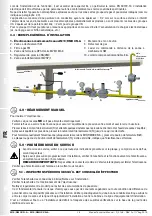
  3.2 - INSTALLATION 

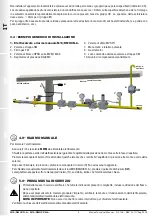
(see example in 3.4) 

• Assemble the device by screwing it, with the due seals, onto the plant with pipes and/or fittings with the right threading for 

the connection being attached. 

• Do not use the coil (

4

) as a lever to help you screw it on, only use the specific tool; 

• The arrow, shown on the body (

11

) of the device, needs to be pointing towards the application;

• The device can also be installed vertically without prejudicing the correct operation. It cannot be put in 

upside down (with the reset knob (

1

) pointing downwards);

• During installation, avoid debris or metal residues from getting into the device;

• To guarantee mechanical tension-free assembly, we recommend using compensating joints, which also 

adjust to the pipe’s thermal dilation;

• If the device is to be installed in a ramp, it is the installer’s responsibility to provide suitable supports or correctly sized 

supports, to properly hold and secure the assembly. Never, for any reason whatsoever, leave the weight of the ramp only on 

the connections (flanged or threaded) of the individual devices;

• In any case, following installation, check the tightness of the plant;

• ATTENTION:

 The coil is provided with a 3m long power supply cable (

3

). This cable 

CANNOT

 be replaced with a 

different one. In the event of damage, the part (coil) must be disposed of and replaced with an identical new one; Any repair 

(if possible) can only be carried out by the manufacturer;

• In the dangerous zone, wire the ends of the cable with explosion-proof approved equipment (E.g. Terminal box with “E” 

protection or increased safety according to EN 60079-7) using the special wire terminals;

• Cable colours 


Phase   : brown (alternatively black or grey)


Neutral  : blue


: yellow/green

• Make sure the connection cables are inserted correctly into the electrical terminal, ensuring they are not crushed and/or 

damaged in order to prevent short circuits and interferences.

• Provide a fixed installation ensuring adequate protection against mechanical stress;

• The valve needs to be connected to earth either through the pipe or through other means (e.g. cable jumpers).

Special conditions for safe use

The “X” symbol (positioned at the end of the protection mode) indicates particular conditions of use:

•  Clean the product regularly to prevent dust from building up;

•  The valve must be installed in places at a low risk of mechanical impact;

•  Minimum bending radius of the cable = 4 Ø; minimum installation temperature -35°C;

•  The equipment must be protected against the effect of lightning discharges;

•  Sparks caused by impact or friction on light metals can cause sources of ignition, therefore tools with corroded surfaces 

must not be used under any circumstances (e.g. for adjustments, maintenance, etc.);

•  Protect the product from impact or friction caused by other objects;

•  Periodically check the integrity of the dissipative surface treatment of the coil and connector;

•  Do not install in environments where the product is in direct contact with corrosive gases, chemicals, salt water, water or 

steam (C3 or medium degree of environmental pollution). Contact the technical department for any other application, for 

the compatibility analysis;

3.3 - INSTALLATION IN PLACES WHERE THERE IS THE RISK OF EXPLOSION (DIRECTIVE 2014/34/EU)

The solenoid valve complies with Directive 2014/34/EU as a device of group II, category 3G and as device of group II, category 

3D; consequently, it is suited for installation in zones 2 and 22 as classified in Annex I of Directive 99/92/EC. The solenoid 

valve is 

NOT

 suitable for use in zones1, 21, 0 and 20, as defined in aforementioned Directive 99/92/EC. To determine the 

qualification and size of the hazardous zones, please refer to standard IEC EN 60079-10-1.

If installed and subject to maintenance in full compliance with all conditions and technical instructions provided in this manual, the 

device does not pose a source of specific hazards: in particular, under conditions of normal operation, it is not expected for the 

solenoid valve to emit a flammable substance into the atmosphere with methods such as to originate an explosive atmosphere.

During installation and maintenance, it is imperative to comply with the Ex standards, in particular EN 60079-14. Electrical 

installation must be carried out by authorised personnel in accordance with relative national regulations.
Do not install the appliance in explosive atmospheres except for the specified gas and dust groups and areas (as explained 
in section 2.0).

Summary of Contents for M16/RMOX N.A.

Page 1: ...A E S MADE IN ITALY 0497 II3G II3D ATEX II 3G II 3D I T E N F R E S Pressione massima di esercizio Maximum operating pressure Pression maximum de fonctionnement Presi n m xima de funcionamiento 6 bar...

Page 2: ...gni Drawings Dessins Dise os 27 Dimensioni tabella 1 Dimensions table 1 Dimensions tableau 1 Dimensiones tabla 1 29 Bobine di ricambio tabella 2a 2b 30 Spare coils table 2a 2b Bobines de rechange tabl...

Page 3: ...ome elemento sostitutivo di un rubinetto a chiusura manuale 1 2 LEGENDA SIMBOLI ATTENZIONE Viene richiamata l attenzione su dettagli tecnici rivolti al personale qualificato PERICOLO In caso di inosse...

Page 4: ...la pressione massima dichiarata sull etichetta del prodotto Eventuali tappi di protezione se presenti vanno rimossi prima dell installazione Tubazioni e interni della valvola devono essere liberi da c...

Page 5: ...icurando un adeguata protezione contro le sollecitazioni meccaniche La valvola deve essere collegata a terra tramite la tubazione o mediante altri mezzi es ponti a cavi Condizioni speciali per un uso...

Page 6: ...ra interno centrale termica tettoiaesterna rete utenza 1 2 8 9 10 3 4 5 6 7 7 4 0 RIARMO MANUALE Per riarmare l elettrovalvola Assicurarsi che la valvola NON sia alimentata elettricamente Chiudere la...

Page 7: ...al cannotto 2 assieme alle apposite guarnizioni dischetti Inserire nel cannotto 2 la nuova bobina guarnizioni eventuali dischetti e fissare il tutto tramite l apposita vite o dado NOTA Non sono previs...

Page 8: ...N A DN 15 IP65 230 V 50 60 Hz 7 VA P max PS 6 bar TS 20 60 C 0497 year 2017 Lot U1745 25407 00001 II 3G II 3D Modo di protezione II product group 3 product category Gas II 3G Ex mc ec nC IIC T Gc X G...

Page 9: ...ually the gas substituting the manual tap of the gas line allowing also to test at intervals the good working of the solenoid valve 1 2 KEY OF SYMBOLS ATTENTION Attention is drawn to the technical det...

Page 10: ...if any must be removed prior to installation Valve pipes and insides must be clear of any foreign bodies Make sure that the pipe thread is not too long to prevent damaging the body of the device when...

Page 11: ...umpers Special conditions for safe use The X symbol positioned at the end of the protection mode indicates particular conditions of use Clean the product regularly to prevent dust from building up The...

Page 12: ...the solenoid valve Make sure the valve is NOT electrically powered Close the flow downstream of the solenoid valve in order to balance the pressure between upstream and downstream when opening Push th...

Page 13: ...ets discs Place the new coil gaskets any discs inside the armature assembly 2 and secure with the relative screw or nut NOTE No maintenance operations need to be carried out inside the device 7 0 TRAN...

Page 14: ...M16 RMOX N A DN 15 IP65 230 V 50 60 Hz 7 VA P max PS 6 bar TS 20 60 C 0497 year 2017 Lot U1745 25407 00001 II 3G II 3D Protection mode II product group 3 product category Gas II 3G Ex mc ec nC IIC T G...

Page 15: ...ent de remplacement d un robinet fermeture manuelle Normes de r f rence EN 161 EN 13611 EN 60079 0 7 14 15 18 31 1 2 L GENDE DES SYMBOLES ATTENTION Attire l attention sur les d tails techniques s adre...

Page 16: ...ier que la pression de ligne NE D PASSE PAS la pression maximum d clar e sur l tiquette du produit Tout bouchon de protection le cas ch ant doit tre t avant l installation Les tuyaux et l int rieur de...

Page 17: ...ommag s pour viter les courts circuits et les interruptions Pr voir une installation fixe en assurant une protection ad quate contre les contraintes m caniques La vanne doit tre raccord e la terre par...

Page 18: ...pour assurer l quilibre de la pression entre amont et aval lors de l ouverture Presser le bouton rotatif de r armement 1 et attendre quelques instants que la pression entre l amont et l aval de la van...

Page 19: ...des vibrations Si le produit pr sente des traitements de surface ex peinture cataphor se etc ils ne doivent pas tre endommag s pendant le transport La temp rature de transport et de stockage co ncide...

Page 20: ...ssif se r f rant la quantit du lot limination conform ment la Directive D E E E 2012 19 UE Mode de protection II product group 3 product category Gaz II 3G Ex mc ec nC IIC T Gc X G atmosph re explosiv...

Page 21: ...ctrov lvula que puede usarse como elemento sustitutivo de una llave de cierre manual 1 2 LEYENDA DE S MBOLOS ATENCI N Se llama la atenci n sobre detalles t cnicos dirigidos al personal cualificado PRE...

Page 22: ...3 0 PUESTA EN FUNCIONAMIENTO DEL DISPOSITIVO 3 1 OPERACIONES ANTES DE LA INSTALACI N Todas las operaciones de instalaci n deben realizarse en ausencia de atm sfera explosiva Hay que cerrar el gas agu...

Page 23: ...os el componente bobina debe ser eliminado y sustituido por uno id ntico y completo La reparaci n si es posible puede realizarse solo por el fabricante En la zona peligrosa cablee los extremos del cab...

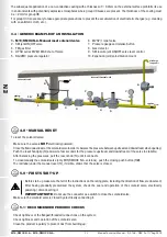
Page 24: ...PSO serie MVB 1 MAX 5 Regulador de presi n RG 2MC 6 V lvula de alivio MVSP 1 7 Man metro y v lvula pulsadora correspondiente 8 Detecci n de gas 9 Palanca de mando a distancia v lvula de corte SM 10 Ju...

Page 25: ...a 4 y qu tela del manguito 2 junto con las juntas discos Coloque en el manguito 2 la nueva bobina juntas cualquier discos y fije todo con el tornillo o tuerca correspondiente NOTA No se prev n operaci...

Page 26: ...la Directiva RAEE 2012 19 UE Mod M16 RMOX N A DN 15 IP65 230 V 50 60 Hz 7 VA P max PS 6 bar TS 20 60 C 0497 year 2017 Lot U1745 25407 00001 II 3G II 3D Modo de protecci n II product group 3 product c...

Page 27: ...27 M16 RMOX N A M16 RMOCX N A Madas Technical Manual 3 3 1bX REV 0 of 1th Aug 2019 IT EN FR ES fig 1 Rp DN 15 Rp DN 20 fig 2 Rp DN 25 3 1 2 4 5 6 7 8 9 10 11 13 3 4 5 6 7 8 9 10 11 12 13 2 1...

Page 28: ...m sealing 10 Sealing washer 11 Valve body 12 Closing manual push button only on M16 RMOCX N A 13 Central pin fig 1 y 2 1 Bot n de rearme 2 Tubo para bobina 3 Cable de alimentaci n 4 Bobina el ctrica 5...

Page 29: ...mm Dimensiones totales en mm Attacchi filettati Threaded connections Raccords filet s Conexiones roscadas A B D E C D E DN 15 66 115 34 20 5 94 5 DN 20 66 115 34 20 5 94 5 DN 25 82 132 44 25 5 106 5...

Page 30: ...Voltaggio Voltage Voltage Voltaje Codice bobina Coil code Code de la bobine C digo de la bobina Timbratura bobina Coil stamp Estampillage de la bobine Marcado de la bobina Potenza assorbita Absorbed...

Page 31: ...A Voltaggio Voltage Voltage Voltaje Codice bobina Coil code Code de la bobine C digo de la bobina Timbratura bobina Coil stamp Estampillage de la bobine Marcado de la bobina Potenza assorbita Absorbed...

Page 32: ...mbar Diagramme calcul avec P1 50 mbar Tabla de p rdidas de carga calculado con P1 50 mbar dv 0 65 dv 1 dv 0 47 dv 1 67 dv densit relativa all aria dv density relative to the air dv densit relative l a...

Page 33: ...dican los di metros de conexi n Es E g Ex Ej RO04VX0000 008 COMBINAZIONI POSSIBILI POSSIBLE COMBINATIONS COMBINAISONS POSSIBLES POSIBLES COMBINACIONES possibile combinare tra di loro le versioni It is...

Page 34: ...OX N A 12 Vdc RO02X0000 001 12 V 50 Hz RO02X0000 004 24 Vdc RO02X0000 005 24 V 50 Hz RO02X0000 003 110 V 50 60 Hz RO02X0000 002 230 V 50 60 Hz RO02X0000 008 DN 20 M16 RMOX N A 12 Vdc RO03X0000 001 12...

Page 35: ...Voltaje P max 6 bar Codice Code Code C dice DN 15 M16 RMOCX N A 12 Vdc ROC02X0000 001 12 V 50 Hz ROC02X0000 004 24 Vdc ROC02X0000 005 24 V 50 Hz ROC02X0000 003 110 V 50 60 Hz ROC02X0000 002 230 V 50 6...

Page 36: ...3289 Fax 39 0442 27821 http www madas it e mail info madas it Ci riserviamo qualsiasi modifica tecnica e costruttiva We reserve the right to any technical and construction changes Nous nous r servons...

Reviews: