background image

10

IT

EN

FR

ES

DN 200 - DN 250 - DN 300

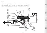
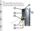
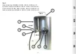
 (see fig. 2 and 3):

• Use the knob (

2

), to insert the eccentric ring nut (

8

) with the larger part of the half moon on the left and the fastening 

grub screw holes facing up;

• Secure the eccentric ring nut (

8

) by tightening the 2 grub screws (

12

);

• Loosen the 2 screws (

9

) of the upper cover (

11

);

• Secure the support bracket (

7

) of the micro switch (

5

) to the upper cover, using the screws (

9

);

• Tighten or loosen the micro switch (

5

) for calibration so that when the solenoid valve is closed, the micro switch’s pin (

4

) is pressed;

• Secure the micro switch (

5

) in that position by tightening the 2 threaded grub screws (

6

);

• The kit is now installed. Reset and close the solenoid valve (by cutting off the power) to make sure the microswitch is 

signalling correctly.  Repeat the operation 2-3 times;

• Position the cover of the knob (

3

) and secure it in that position with the screw (

10

).

3.0 - TRANSPORT, STORAGE AND DISPOSAL

•  During transport the material needs to be handled with care, avoiding any impact or vibrations to the device;

•  If the product has any surface treatments (ex. painting, cataphoresis, etc) it must not be damaged during transport;

•  The transport and storage temperatures must observe the values provided on the rating plate;

•  If the device is not installed immediately after delivery it must be correctly placed in storage in a dry and clean place;

•  In humid facilities it is necessary to use driers or heating to avoid condensation.

•  At the end of its service life, the product is to be disposed of separately from other waste (WEEE directive 2012/19/EU) 

and in compliance with the legislation in force in the country where this operation is performed.

4.0 - WARRANTY

The warranty conditions agreed with the manufacturer at the time of the supply apply.

For damage caused by:

• Improper use of the device;

• Failure to observe the requirements described herein;

• Failure to observe the regulations pertaining to installation;

• Tampering, modification and use of non-original spare parts;

are not covered by the rights of the warranty or compensation for damage.

The warranty also excludes maintenance work, other manufacturers’s assembling units, making changes to the device and natural wear. 

Summary of Contents for Madas IT262.00

Page 1: ...omologaci n CE seg n EN 161 conforme Reglamento UE 2016 426 0051 MICROSWITCH INDICATORE POSIZIONE DI CHIUSURA CPI SWITCH CLOSED POSITION INDICATOR SWITCH CPI SWITCH MINIRUPTEURINDICATEURDELAPOSITIONDE...

Page 2: ...2 IT EN FR ES INDICE INDEX INDEX NDICE pag Italiano 3 English 7 Fran ais 11 Espa ol 15 Disegni Drawings Dessins Dibujos 19...

Page 3: ...e utilizzando indirizzo e recapiti telefonici riportati in ultima pagina 1 1 DESCRIZIONE Il microswitch di segnalazione posizione di chiusura CPI SWITCH un sensore che fornisce una segnalazione alla c...

Page 4: ...tilizzati SOLAMENTE quelli indicati dal fabbricante L utilizzo di componenti differenti oltre a far decadere la garanzia del prodotto potrebbe compromettere il corretto funzionamento dello stesso Il f...

Page 5: ...manopola in dotazione al kit La manopola 2 dev essere inserita con il foro filettato rivolto verso l alto e facendo coincidere tale foro filettato col foro del perno Fissare la manopola 2 avvitando e...

Page 6: ...olpi o vibrazioni Se il prodotto presenta trattamenti superficiali es verniciatura cataforesi ecc non devono essere danneggiati durante il trasporto La temperatura di trasporto e di stoccaggio coincid...

Page 7: ...manufacturer from the address and phone numbers provided on the last page 1 1 DESCRIPTION The closed position indicator switch CPI SWITCH is a switch with normally open contact that provides a signal...

Page 8: ...ufacturer recommended parts can be used Using different parts not only voids the product warranty it could compromise correct device operation The manufacturer is not liable for malfunctions caused by...

Page 9: ...ied with the kit The knob 2 must be inserted with the threaded hole facing up and making said threaded hole match up with the pin hole Secure the knob 2 by tightening and securing the grub screw 1 ins...

Page 10: ...act or vibrations to the device If the product has any surface treatments ex painting cataphoresis etc it must not be damaged during transport The transport and storage temperatures must observe the v...

Page 11: ...adresse et les num ros de t l phone report s dans la derni re page 1 1 DESCRIPTION Le micro interrupteur de signalisation de la position de fermeture CPI SWITCH est un capteur qui fournit une signalis...

Page 12: ...LEMENT ceux indiqu s par le fabricant L utilisation de composants diff rents en plus d annuler la garantie du produit pourrait compromettre le bon fonctionnement de celui ci Le fabricant n est pas res...

Page 13: ...urni avec le kit Le bouton 2 doit tre ins r avec le trou filet vers le haut et en faisant correspondre le trou filet avec le trou de la goupille Fixez le bouton 2 en vissant et en serrant le goujon 1...

Page 14: ...traitements superficiels ex peinture cataphor se etc ils ne doivent pas tre endommag s pendant le transport La temp rature de transport et de stockage co ncide avec celle indiqu e dans les donn es de...

Page 15: ...te a trav s de la direcci n y los n meros de tel fono que aparecen en la ltima p gina 1 1 DESCRIPCI N El microinterruptor de indicaci n de la posici n de cierre MICROINTERRUPTOR CPI es un sensor que a...

Page 16: ...se deben usar SOLO los indicados por el fabricante El uso de componentes diferentes adem s de invalidar la garant a del producto podr a perjudicar su correcto funcionamiento El fabricante se exime de...

Page 17: ...en equipamiento con el kit El bot n 2 debe introducirse con el orificio roscado dirigido hacia arriba y haciendo coincidir dicho orificio roscado con el orificio del perno Fije el bot n 2 enroscando...

Page 18: ...lpesovibraciones Si el producto presenta tratamientos superficiales ej pintura cataforesis etc no se deben da ar durante el transporte La temperatura de transporte y almacenamiento debe coincidir con...

Page 19: ...DN 150 con CPI Approximate drawing for M16 RM N C DN 65 DN 80 DN 100 DN 125 DN 150 with CPI Dessins indicatifs pour M16 RM N C DN 65 DN 80 DN 100 DN 125 DN 150 avec CPI Dise os orientativos para M16 R...

Page 20: ...per M16 RM N C DN 200 DN 250 DN 300 con CPI Approximate drawing for M16 RM N C DN 200 DN 250 DN 300 with CPI Dessins indicatifs pour M16 RM N C DN 200 DN 250 DN 300 avec CPI Dise os orientativos para...

Page 21: ...N 200 DN 250 DN 300 con CPI Approximate drawing for M16 RM N C DN 200 DN 250 DN 300 with CPI Dessins indicatifs pour M16 RM N C DN 200 DN 250 DN 300 avec CPI Dise os orientativos para M16 RM N C DN 20...

Page 22: ...o coperchio superiore 10 Vite di fissaggio coperchio di protezione 11 Coperchio superiore 12 Grani fissaggio ghiera eccentrica fig 1 2 and 3 1 Knob clamping grub screw 2 Reset knob 3 Protective cover...

Page 23: ...e fixation couvercle de protection 11 Couvercle sup rieur 12 Goujons de fixation anneau excentrique fig 1 2 y 3 1 Bul n de fijaci n del bot n 2 Bot n de rearme 3 Tapa de protecci n 4 Perno microinterr...

Page 24: ...Tel 39 0442 23289 Fax 39 0442 27821 http www madas it e mail info madas it Ci riserviamo qualsiasi modifica tecnica e costruttiva We reserve the right to any technical and construction changes Nous n...

Reviews: