9
IT
EN
FR
ES
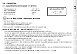
2.0 - CPI SWITCH
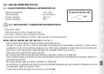
2.1 - CPI SWITCH TECHNICAL DATA
• Ambient temperature
: -20 ÷ +60 °C
• Switchable voltage
: max 250 V (Vac)
• Switchable current
: max 2 A
• Protection rating
: IP67
2.2 - CPI SWITCH INSTALLATION and CALIBRATION
• black cable: common
• red cable: signal with micro switch not pressed
• white cable: signal with micro switch pressed
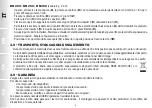
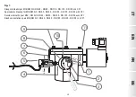
You must proceed as follows to install the CPI kit in on the solenoid valve:
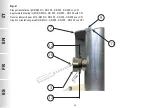
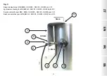
DN 65 - DN 80 - DN 100 - DN 125 - DN 150
(see fig. 1):
• Loosen the fastening screw (
1
) inside the reset knob (
2
) and remove it;
• In the pin without the knob, insert the eccentric grub screw (
8
) with the larger part of the half moon on the left, and the new
knob supplied with the kit. The knob (
2
) must be inserted with the threaded hole facing up and making said threaded hole
match up with the pin hole. Secure the knob (
2
) by tightening and securing the grub screw (
1
) inside;
• Loosen the 2 screws (
9
) of the upper cover (
11
);
• Secure the upper cover (
11
) to the support bracket (
7
) of the micro switch using the 2 screws (
9
);
• Tighten or loosen the micro switch (
5
) for calibration so that when the solenoid valve is closed, the micro switch pin (
4
)
is pressed;
• Secure the micro switch (
5
) in that position by tightening the 2 threaded grub screws (
6
);
• The kit is now installed. Reset and close the solenoid valve (by cutting off the power) to make sure the microswitch is
signalling correctly. Repeat the operation 2-3 times;
• Position the protective cover of the knob (
3
) and secure it in that position with the screw (
10
).
CPI electrical diagram
SPDT


