IT
EN
FR
ES
11
Madas Technical Manual
- 4|4.1b - REV. 0 of 10
th
May 2018
RG/2M
• If, after installing the gaskets, there is still an excessive space in between, do not try to reduce said gap by excessively
tightening the bolts of the device;
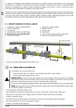
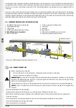
• The arrow, shown on the body (
6
) of the device, needs to be pointing towards the application;
• Insert the relative washers inside the bolts in order to prevent damage to the flanges during tightening;
• When tightening, be careful not to “pinch” or damage the gasket;
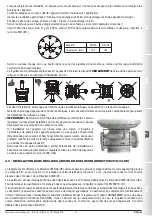
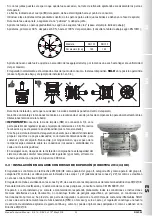
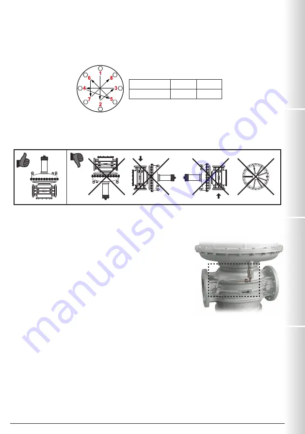
• Tighten the nuts or bolts gradually, in a “cross” pattern (see the example below);
• Tighten them, first by 30%, then by 60% and finally 100% of the maximum torque (see the table below according to EN 13611);
Diameter
DN 125
DN 150
Max. torque (N.m)
160
160
• Tighten each nut and bolt again clockwise at least once, until the maximum torque has been achieved uniformly;
• The regulator is normally positioned before the application.
ONLY
install the device in the position permitted (see the figure
below and installation example in 3.4);
• During installation, avoid debris or metal residues from getting into the device;
• To guarantee mechanical tension-free assembly, we recommend using compensating joints, which also adjust to the pipe’s
thermal expansion;
• IMPORTANT:
connect the pulse outlet (
13
) with a G 3/8 fitting downstream of
the regulator (see installation example in 3.4). Do not make the connection if it is
already present on the device (see photo on the side);
• If the device needs to be installed in a ramp, it is the installer’s responsibility
to provide suitable supports or correctly sized supports to properly hold and
secure the assembly. Never, for any reason whatsoever, leave the weight of the
ramp resting only on the connections (threaded or flanged) of the individual
devices;
• In any case, after installation check the tightness of the system, without
subjecting the membrane of the regulator (therefore, the downstream pipe
section) to a pressure higher than 300 mbar.
3.3 - INSTALLATION IN PLACES WHERE THERE IS THE RISK OF EXPLOSION (DIRECTIVE 2014/34/EU)
The regulator complies with Directive 2014/34/EU as a group II equipment, category 2G and as group II equipment, category
2D; consequently, it is suited for installation in zones 1 and 21 (besides zones 2 and 22) as classified in Annex I of Directive
99/92/EC.
The regulator is not suited for use in zones 0 and 20 as defined in the aforementioned Directive 99/92/EC.
To determine the qualification and size of the danger zones, please refer to standard IEC EN 60079-10-1.
If the device is installed and serviced in full compliance with all the conditions and technical instructions provided in this
document, it does not pose a source of specific hazards: in particular, under normal operating conditions, the regulator emits
a flammable substance into the atmosphere ONLY if the working membrane (
15
) malfunctions: in which case (and only if) the
regulator constitutes a source of emission of explosive atmosphere of continuous degree and, as such, can generate danger
zones 99/92, as defined in Directive 99/92/EC.


