2
RG/2MCS - RG/2MBZ
DN 65 - 80 - 100
© 2011 MADAS s.r.l.
Capitolo - Chapter
Chapìtre - Capitulo
22.2
RIDUTTORI DI PRESSIONE PER GAS CON OTTURATORE COMPENSATO AD AZIONE DIRETTA TIPO RG/2MCS - RG/2MBZ
DIRECT OPERATED GAS PRESSURE REGULATOR WITH COMPENSATED OBTURATOR TYPE RG/2MCS - RG/2MBZ
REDUCTEUR DE PRESSION DU GAZ AVEC OBTURATEUR COMPENSE A ACTION DIRECTE TYPE RG/2MCS - RG/2MBZ
REDUCTOR DE PRESIÓN PARA GAS CON OBTURADOR COMPENSADO DE ACCIÓN DIRECTA TIPO RG/2MCS - RG/2MBZ
Manuale Tecnico 2011
Capitolo 22.2 (Rev. 0)
2011 Technical Manual
Chapter 22.2 (Rev. 0)
Manuel Technique 2011
Chapitre 22.2 (Rev. 0)
Manual Técnico 2011
Capítulo 22.2 (Rev. 0)
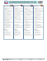
CARATTERISTICHE TECNICHE
• Impiego: gas non aggressivi delle 3 famiglie
(gas secchi)
• Attacchi flangiati PN 16:
DN 65 ÷ DN 100 secondo ISO 7005
• Su richiesta attacchi flangiati ANSI 150
• Pressione max esercizio: 5 bar
• Temperatura ambiente: -20 ÷ +60 °C
• Temperatura superficiale max: 60 °C
• Classe accuratezza P2 (
AC
): 10
• Gruppo accuratezza blocco sovrapressione
(
AG
): 10
• Classe pressione di chiusura (
SG
): 30
• Campo pressione intervento:
vedere tabella molle
• Tempo di chiusura blocco: < 1 s
• Valvola di sfioro: testata secondo indicazioni
riportate su EN 334
• Connessione dello sfiato: G 3/4”
• Resistenza meccanica: Gruppo 2
(secondo EN 13611:2007)
• Fattore di sicurezza: f=4 (5*4 = 20 bar)
secondo EN 88-2 punto 7.2
MATERIALI
• Alluminio pressofuso
(UNI EN 1706)
• Ottone OT-58 (UNI EN 12164)
• Alluminio 11S (UNI 9002-5)
• Acciaio INOX (UNI EN 10088)
• Gomma antiolio NBR (UNI 7702)
TECHNICAL DATA
• Use: not aggressive gases of the 3 families
(dry gases)
• Flanged connections PN 16:
DN 65 ÷ DN 100 according to ISO 7005
• On request ANSI 150 flanged connections
• Max. working pressure: 5 bar
• Environment temperature: -20 ÷ +60 °C
• Max superficial temperature: 60 °C
• P2 accuracy class (
AC
): 10
• Overpressure lockout accuracy group
(
AG
): 10
• Closing pressure class (
SG
): 30
• Trip pressure range: see springs table
• Shut off closure time: < 1 s
• Relief valve: tested according to EN 334
• Vent connection: G 3/4”
• Mechanical strength:
Group 2 (according to EN 13611:2007)
• Safety factor: f=4 (5*4 = 20 bar)
according to EN 88-2 point 7.2
MATERIALS
• Die-cast aluminium
(UNI EN 1706)
• OT-58 brass (UNI EN 12164)
• 11S aluminium (UNI 9002-5)
• Stainless steel (UNI EN 10088)
• NBR rubber (UNI 7702)
DATOS TÉCNICOS
• Utilizo: gas no agresivos de las 3 familias
(gas secos)
• Enganches con bridas PN 16:
DN 65 ÷ DN 100 en conformidad con ISO 7005
• Bajo pedido enganches con bridas ANSI 150
• Presión Máx. de trabajo: 5 bar
• Temperatura ambiente: -20 ÷ +60 °C
• Temperatura superficial Máx.: 60 °C
• Clase de precisión P2 (
AC
): 10
• Grupo de precisión bloqueo exceso de
presión (
AG
): 10
• Clase presión de cierre (
SG
): 30
• Campo presión intervención: véase tabla
muelle
• Tiempo cierre bloqueo: < 1 s
• Válvula de alivio: testada en conformidad
con EN 334
• Conexión del respiradero: G 3/4”
• Resistencia mecánica: Grupo 2
(en conformidad con EN 13611:2007)
• Factor de seguridad: f=4 (5*4 = 20 bar)
en conformidad con EN 88-2 punto 7.2
MATERIALES
• Aluminio vaciadizo a presión
(UNI EN 1706)
• Latón OT-58 (UNI EN 12164)
• Aluminio11S (UNI 9002-5)
• Acero inoxidable (UNI EN 10088)
• Goma antiaceite (UNI 7702)
CARACTERISTIQUES TECHNIQUES
• Emploi: gaz non corrosifs des 3 familles
(gaz secs)
• Connecteurs flangés PN 16:
DN 65 ÷ DN 100 selon ISO 7005
• Sur demande connexions flangées ANSI 150
• Pression de fonctionnement max.: 5 bar
• Température ambiant : -20 ÷ +60 °C
• Température superficielle max.: 60 °C
• Classe de précision P2 (
AC
): 10
• Ensemble arrêt en cas de surpression
(
AG
): 10
• Classe pression de fermeture (
SG
): 30
• Gamme intervention pression: voir tableau
des ressorts
• Temps de fermeture arrêt: < 1 s
• Valve de sécurité: testée selon les
références EN 334
• Connecteur d’évacuation: G 3/4”
• Résistance mécanique: Groupe 2
(selon EN 13611:2007)
• Facteur de sécurité: f=4 (5*4 = 20 bar)
selon EN 88-2 point 7.2
MATERIELS
• Aluminium fondé dans la masse
(UNI EN 1706)
• Laiton OT-58 (UNI EN 12164)
• Aluminium 11S (UNI 9002-5)
• Acier INOX (UNI EN 10088)
• Caoutchouc anti-huile NBR (UNI 7702)


