ES
FR
EN
IT
14
Madas Technical Manual
- 5|5.2a - REV. 0 of
th
Apr 2019
RG/2MCS - RG/2MBZ
If the device is threaded:
make sure that the pipe thread is not too long, to prevent damaging the body of the device when screwing it on;
If the device is flanged:
• make sure the inlet and outlet counter-flanges are perfectly coaxial and parallel in order to prevent unnecessary
mechanical stress to the body. Also calculate the space to insert the seal gasket;
• With regard to tightening operations, equip yourself with one or two calibrated torque wrenches or other controlled locking
tools;
• With outdoor installation, it is advisable to install a protective roof to prevent rain from oxidising or damaging parts of the
device.
• According to the plant geometry, check the risk of an explosive mixture arising inside the piping;
• If the regulator is installed near other devices or as part of an assembly, compatibility between the regulator and
these devices must be evaluated beforehand;
• Provide protection against impact or accidental contact if the device is accessible to unqualified personnel.
3.2
INSTALLATION
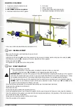
(see examples in 3.4)
Threaded devices:
• Assemble the device by screwing it, with the due seals, onto the plant with pipes and/or fittings whose threads are consistent
with the connection being attached;
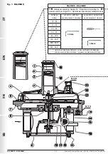
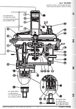
• Do not use the neck of the top cover (
25
) as a lever to help you screw it on, but only use the specific tool;
• The arrow, shown on the body (
20
) of the device, needs to be pointing towards the application;
Flanged devices:
• Assemble the device by flanging it, with the due seals, onto the plant with pipes whose flanges are consistent with the
connection being attached. The gaskets must be free from defects and must be centred between the flanges;
• If, after installing the gaskets, there is still an excessive space in between, do not try to reduce the
said gap by excessively tightening the bolts of the device;
• The arrow, shown on the body (
20
) of the device, needs to be pointing towards the application;
• Insert the relative washers inside the bolts in order to prevent damage to the flanges during
tightening;
• When tightening, be careful not to “pinch” or damage the gasket;
• Tighten the nuts or bolts gradually, in a “cross” pattern
(see the example alongside);
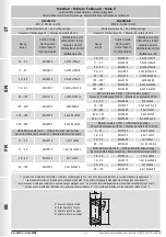
• Tighten them, first by 30%, then by 60% and finally 100% of the maximum
torque (see the example alongside, according to EN 13611);
• Tighten each nut and bolt again clockwise at least once, until the maximum torque has been achieved uniformly;
Common procedures (threaded and flanged devices):
• The regulator is normally positioned before the application. Previously evaluate the possibility of installing the regulator as
shown in the installation example in 3.4;
• It can be installed in any position even if the installation shown in 3.4 (installation examples) is preferred. A pressure outlet (
19
)
can be found outside the regulator, downstream from it, to control the regulation pressure (Pa);
• It is necessary to connect the pulse outlet with a G 1/4 fitting downstream of the regulator (see installation examples). To
do so, remove the cap (
21
);
• Drain the relief valve (if any) outwards (as shown in 3.4) by removing the dust cap (
24
);
• It is always recommended to install a compensation joint;
• During installation, avoid debris or metal residues from getting into the device;
• To guarantee mechanical tension-free assembly, we recommend using compensating joints, which also adjust to the pipe’s
thermal expansion;
• If the device is to be installed in a ramp, it is the installer’s responsibility to provide suitable supports or correctly sized
supports, to properly hold and secure the assembly. Never, for any reason whatsoever, leave the weight of the ramp only on
the connections (threaded or flanged) of the individual devices;
• In any case, after installation check the tightness of the system, without subjecting the diaphragm of the regulator (therefore,
the downstream pipe section) to a pressure higher than 300 mbar (valid only for versions with standard working diaphragm).
For versions with reinforced diaphragm, check the tightness with a pressure equal to 1.5 times the regulator setting pressure.
Diameter
DN 32 DN 40 DN 50
Max. torque (N.m)
50
50
50


