IT
EN
FR
ES
15
Madas Technical Manual
- 5|5.2a - REV. 0 of
th
Apr 2019
RG/2MCS - RG/2MBZ
3.4
GENERAL EXAMPLES OF INSTALLATION
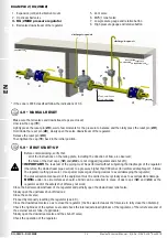
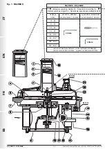
EXAMPLE 1 (RG/2MCS)
1. Expansion joint/anti-vibration mount
2. Upstream ball valve
3. FM gas filter
4. OPSO series MVB/1 MAX shut off valve
5. RG/2MCS pressure regulator
3.3
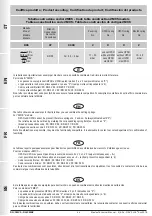
INSTALLATION IN PLACES WHERE THERE IS THE RISK OF EXPLOSION (DIRECTIVE 2014/34/EU)
The regulator complies with Directive 2014/34/EU (formerly 94/9/EC) as group II equipment, category 2G and as group II
equipment, category 2D; consequently, it is suited for installation in zones 1 and 21 (in addition to zones 2 and 22) as classified
in Annex I of Directive 99/92/EC. The regulator is not suited for use in zones 0 and 20 as defined in the aforementioned Directive
99/92/EC. To determine the qualification and size of the danger zones, please refer to standard IEC EN 60079-10-1.
If installed and subject to maintenance in full compliance with all conditions and technical instructions provided in this manual,
the device does not pose a source of specific hazards: in particular, under conditions of normal operation, the regulator is
expected to emit a flammable substance into the atmosphere only occasionally, and specifically:
The regulator can be dangerous with respect to the presence of other devices nearby if the integrated relief valve is triggered
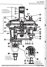
or if the working diaphragm (
22
) or the blocking diaphragm (
27
) fails. If the diaphragm fails, the regulator becomes a source
of explosive atmosphere emission of continuous degree and, as such, it can generate hazardous areas 0 as defined in Directive
99/92/EC.
In particularly critical installation conditions (unattended areas, poor maintenance or poor ventilation) and especially if there are
potential sources of ignition and/or hazardous equipment near the regulator in regular operation, as they may generate electric
arcs or sparks, a preliminary assessment of the compatibility between the regulator and such equipment must be carried out.
In any case, every useful precaution must be adopted so as to prevent the regulator from generating zones 0: for example,
annually verify regular operation, possibility of changing the degree of emission of the source or intervening on the explosive
substance discharge by directing it outwards. To do so, simply remove the dust caps (
12
) and (
24
) by connecting the specific
pipe (respectively, G 3/8 and G 1/8) conveyed to the outside (see installation examples in 3.4).
piping
application
discharge in
open air
1
2
3
6
5
7
8
9
10
4
internal thermal unit
non-hazardous ventilated zone*
external roof
* if the zone is ATEX classified follow the indications of 3.3
6. Ball valve downstream of the regulator
7. Vent valve
8. MVS/1 relief valve
9. Low pressure gauge and relative button
10. High pressure gauge and relative button
Ø ext. min 8mm
Ø int. min 6mm
5 DN


