IT
EN
FR
ES
17
Madas Technical Manual
- 5|5.2a - REV. 0 of
th
Apr 2019
RG/2MCS - RG/2MBZ
6.0
SETTING
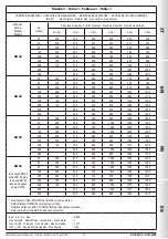
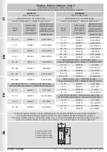
Before carrying out the operations, make sure that the supplied spring/s is/are suitable for the desired Pa - OPSO - UPSO and
differential relief valve fields.
6.1 - Adjusting the maximum pressure shut off (OPSO)
• Unscrew the cap (
11
);
• Use the supplied key (
32
) to fully tighten the adjustment ring nut of the maximum shut off (
28
);
• Start the system, reset the shut off device as indicated in 4.0 and make sure that there is no gas consumption (close the
applications downstream of the regulator);
Method 1:
1. Loosen and remove caps (
26
) and (
11
);
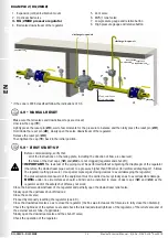
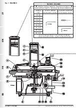
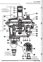
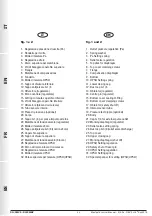
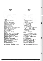
2. Use an 8 mm socket wrench (see fig. 1a and 2a) to press on the nut (
4
), slowly increasing the downstream pressure
to the desired value and simultaneously keep the nut (
4
) pressed; use the key supplied (
32
) to loosen the ring nut
(
28
) until the device is triggered;
3. Tighten the caps back to their original position and repeat the Pa setting steps;
Method 2:
1. Alternatively, use an auxiliary gas pressure to slowly increase the downstream pressure to the desired value and
simultaneously, use the key supplied (
32
) to loosen the ring nut (
28
) until the device is triggered (so as to avoid
having to set the Pa again);
• In both cases, reset the system by following the correct procedure and verify that the trigger value is that desired by repeating
the release step 2-3 times;
• If necessary, adjust the trigger value by turning the ring nut (
28
) with the specific key (
32
).
6.2 - Adjusting the minimum pressure shut off (UPSO)
• Unscrew the cap (
11
);
• Use the key supplied (
32
) to loosen the adjustment ring nut of the minimum shut off (
30
) to the minimum;
• Start the system and reset the shut off device as described in 4.0;
• Reduce the downstream pressure to the desired trigger value;
• Use the key supplied (
32
) to tighten the adjustment ring nut (
30
) until the minimum pressure shut off is triggered.
• Reset the system by following the correct procedure and verify that the trigger value is that desired by repeating the release
step 2-3 times;
• If necessary, adjust the trigger value by turning the ring nut (
30
) with the specific key (
32
);
6.3 - Adjusting the relief valve (differential DfRv)
NOTE
: The relief valve (if any) in these regulators is differential, therefore the range value (DfRv) indicated must be added to
the range value of the outlet pressure (Pa).
Example: Pa=32
-
60 mbar - DfRv=15
-
40 mbar.
Means that the relief valve can be calibrated from: (Pa min + DfRv min) = 32+15=47 mbar to: (Pa max + DfRv max) =
60+40=100 mbar
Therefore the effective range of the relief valve (in this case) is 47
-
100 mbar.
• Start the system and set the shut off as described in point 4.0;
• Slowly close the valve downstream of the regulator;
• Loosen and remove the cap (
26
);
• Use the 8 mm socket spanner (see fig. 1 and 2) to fully tighten the nut (
4
);
• Use the 8 mm socket spanner to press the adjustment nut (
4
) and increase the pressure Pa, reading it on the pressure gauge,
up to the desired setting value;
• Without pressing further, slowly loosen the adjustment nut (
4
) until the pressure Pa begins to decrease, shown on the
pressure gauge;
• In this case, the relief valve is set to the desired value;
• Remove the socket spanner and close the cap (
26
).


