6
Jacked Up
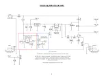
You should use the jack spec’d in the schematic (linked in the Mouser BOM). It actually doesn’t matter if you use a stereo
or mono jack since the ring portion of the stereo jack is not connected to anything. It
does
, however, require this particular
“sleeve make” setup to connect DC ground.
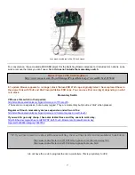
A “sleeve make” jack – the sleeve contacts the switched pin to make the DC Ground connection.
If you do not use a sleeve make jack (the “sleeve normal” jack, for instance), then you will need to short the sleeve and
switched pin together as shown below.
Here the sleeve and switched pin are shorted together with a buss wire for DC ground.
One last word about jacks: whether you use the “sleeve make” or “sleeve normal”
you must use a Neutrik
.
Other jacks have the same pin spacing but slightly different tolerances in their casings and will not fit properly. Again, links
to the proper jacks are in the BOM.
Finally, you might realize at this point that the entire circuit it ground isolated. IOW, there is no chassis grounding point
with the Switching Board or the hardware attached to it (same goes for the audio boards). Therefore, we need to create a
ground path to the chassis.
Peter demonstrates his method in the video linked on pg.2 I suggest you watch the video and see how he does it (using a
small bead of solder on the jack ferrule to ensure sleeve to chassis contact). No issue with doing it that way at all, but here
is an alternative (I find this easier).
Use the ½” lock washer you get with foot-switches (some a serrated, others are link...doesn’t matter) and solder a wire to
it. Solder the other end to the sleeve of the DC Jack. So, when your foot-switch is locked down the washer contacts the
chassis and makes the ground connection. Either method is fine…it’s up to your personal preference
Note
While you can get around using the “sleeve make” jack if you don’t have them, you will not be able to use a battery.
When you wire the sleeve and switched sleeve together, removing the input jack will not disconnect the battery power
and therefore it will drain quickly. But, you shouldn’t be using a battery anyway…they are wasteful and damaging to
the environment unless properly recycled!


