Version: User’s manual EN NF-Walker 2 ver. 2.0
Date for this version: 09.02.2017
Page 9 of 56
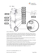
The front axle (12) is equipped with horizontal wheels (14) that will function as wall guards if the
undercarriage is colliding into furniture or walls.
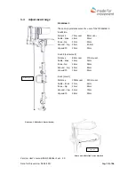
The rear axle (18) is connected to a trailing arm (17) which is suspended by a damper (6). The
damper (6) is adjustable in length and stiffness. The damper (6) can be delivered with four different
configurations:
soft
medium soft
medium hard
hard
The front axle (12) is connected to the front axle frame part (13) which is clamped in place in the
main frame (10). Underneath the front axle (12), there is two rollers (11) for guidance of the guide
straps/elastics. The front axle of the NF-Walker 2 can be delivered in two widths. The front axle
frame part (13) is adjustable in length totally 110mm. The main frame (10) is the connection point
for all forces picked up by the undercarriage and is connecting the different parts of the
undercarriage together.
A column (2) with a fix plate (1) is placed vertically in the main frame (10). The fix plate (1) is the
fixation point for the brace-system. The column (2) is height adjustable. A height setting screw (5) is
securing the height of the column (2) together with the clamping done by the main frame (10). The
column (2) has a U-tube clamp (9) placed between the height setting screw (5) and the fix plate (1).
The U-tube clamp (9) secures the position of the U-tube (3).
The U-tube (3) is fitted with two rollers (4) for guide straps/elastics.


