background image

2

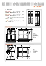
CLASSIFICATION

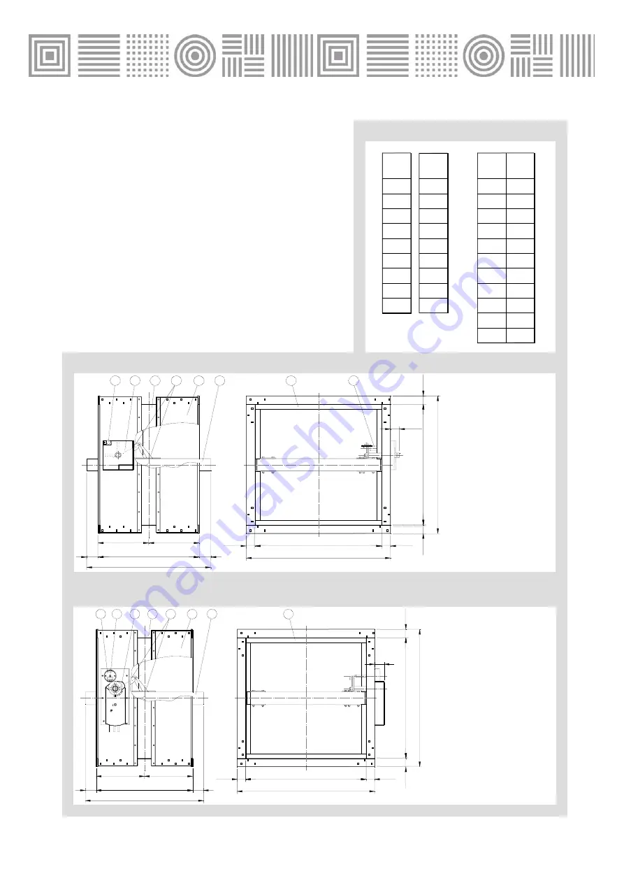
FBK-EIS-120-H

Damper with angled flange 

connection. Blade parallel to the large side.

FBK-EIS-120-V

Damper with angled flange 

connection. Blade parallel to the short side.

…-MA

Manual resetting damper. Is not necessary to 

open the box device.

…-M7F

Damper operated by an actuator with switch 

off device at 24 or 230v.


M A D E L


®

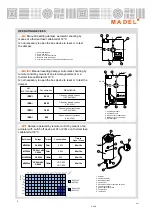
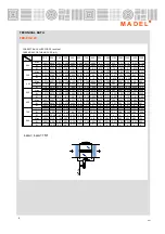
FBK-EIS-120-H-MA

L

200
250
300
350
400
450

500
550
600

700
800

200
250
300
350
400
450

500
550
600
700
800

(mm)

H

(mm)

H1

(mm)

-
-
-
-
-

25

50
75

100
150

200

900

1000
1100
1200
1300
1400
1500

L

(mm)

FBK-EIS-120-H-M7F

SIZES

400

H

L

35

35

35

35

=

=

L + 70

H + 70

H

2

6

4

1

5

7

3

H1

H1

-5

º

45

º

90º

STOP

8

40

35

2

6

4

1

5

7

3

8

H

L

35

35

35

35

L + 70

H +

 70

400

=

=

H

H1

H1

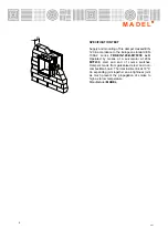
1.Housing
2. Blade
3. Airtightness seal
4. Thermal bridge
5. Transmission roads
6. Manual device
7. Driving switch
8. Thermal fuse

1.Housing
2. Blade
3. Airtightness seal
4. Thermal bridge
5. Transmission roads
6. Actuator
7. Test switch
8. Thermal fuse

4/11

Summary of Contents for FBK-EIS-120

Page 1: ...em It has a symmetrical design that allows wall mounting regardless of air flow The housing is reinforced at the height of the blade with longitudinal angles that give rigidity to the damper The blade...

Page 2: ...0 250 300 350 400 450 500 550 600 700 800 200 250 300 350 400 450 500 550 600 700 800 mm H mm H1 mm 25 50 75 100 150 200 900 1000 1100 1200 1300 1400 1500 L mm FBK EIS 120 H M7F SIZES 400 H L 35 35 35...

Page 3: ...sition lock 5 Connection cable for auxiliary switches 6 Themal fuse cable 7 Power cable connection 8 Thermal fuse 9 Test button 4 11 S1 S2 S3 S4 S5 S6 CLOSED OPEN S1 S2 S3 S4 S5 S6 OUVERT FERM 3 4 5 2...

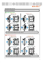
Page 4: ...e bottom Manual device at the top Motorised device at the top FBK EIS 120 MA Manual device at 0 Manual device at 180 Motorised device at 0 Motorised device at 180 1 Wall 2 Actuator PROPER INSTALLATION...

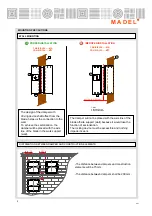
Page 5: ...blade off site support wall because it would lose the function of sectorization The locking device must be accessible and nothing impede its work WALL MOUNTING PROPER INSTALLATION FBK EIS 120 MA FBK E...

Page 6: ...g 120 mm ES FIJACI N INICIO DE MURO GB F IXING WALL SITUATION FR FIXATION D BUT DE MUR IT FISSAGIO INIZIO DEL MURO ES FIJACI N INICIO DE MURO GB FIXING WALL SITUATION FR FIXATION D BUT DE MUR IT FISSA...

Page 7: ...S4 S5 S6 S1 S2 S3 S4 S5 S6 S1 S2 S3 S4 S5 S6 FCC FCA N 3 4 N S1 S2 S3 S4 S5 S6 SIEMENS GNA 326 1E GGA 326 1E SIEMENS GNA 126 1E GGA 126 1E MOTOR 230V CA MOTOR 24V CA 24 48V CC N 1 2 4 11 1 2 3 WALL 1...

Page 8: ...EIS 120 H M7F230 LxH Operated by means of a servomotor at 230v M7F230 start and end of course switches Dampers made from galvanised steel and non combustible board Thermal fusible link at 72 C An exp...

Page 9: ...0 495 0 59 0 270 3 75 0 480 0 58 0 303 3 0 470 800 0 855 9 5 0 088 700 0 865 10 25 0 077 600 0 845 8 75 0 1 900 1000 0 830 8 0 111 Dpt Pa 0 33 4 0 22 0 45 0 44 0 39 2 25 0 54 0 57 0 33 2 75 0 46 1100...

Page 10: ...00 3000 3500 6500 8000 4 5 6 7 8 9 0 4 0 2 Kr 1 0 8 0 6 10 2 35 40 45 50 L wa1 dB A 1 1 5 3 4 2 Vf m s 1 5 2 3 4 5 6 7 8 9 10 0 15 0 02 DPt Pa 30 15 20 10 100 60 80 40 0 06 0 05 0 03 0 04 0 08 0 1 0 8...

Page 11: ...11 M A D E L 4 11...
Reviews: