5
M A D E L
®
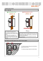
MOUNTING PRECAUTIONS
The design of the damper with
driving device shaft offset from the
blade, helps us the connection to the
wall.
To achieve the sectorization, the
damper will be placed with the axis
line of the blade in the work support
(wall).
1
2
3
The damper will not be placed with the axis line of the
blade off-site support (wall) because it would lose the
function of sectorization.
The locking device must be accessible and nothing
impede its work.
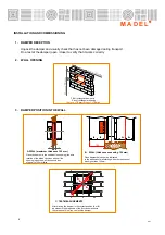
WALL MOUNTING
PROPER INSTALLATION
FBK-EIS-120-…-MA
FBK-EIS-120-…-M7F
1
2
3
FBK-EIS-120-…-MA
FBK-EIS-120-…-M7F
IMPROPER INSTALLATION
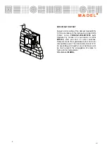
DISTRIBUTION BETWEEN DAMPER AND CONSTRUCTION ELEMENTS
-The distance between dampers and construction
elements will be 75mm.
-The distance between dampers shall be 200 mm.
200
75
20
0
1. Wall
2. Locking device
3. Axis of the blade
4/11
NOT PROTECTED ZONE
Summary of Contents for FBK-EIS-120
Page 11: ...11 M A D E L 4 11...


