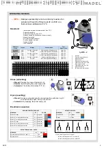
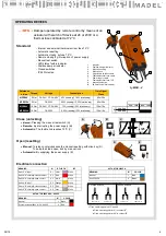
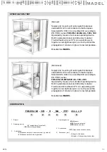
background image

TECHNICAL DATA

FOK-EIS-120

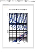
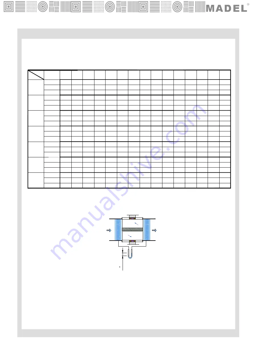
FREE AREA  FOR THE AIR  PASS (m

2

) / CORRECTION  VALUES  FOR DPt, Lwa

14

02/18

100

1,070

-24

0,007

0,013

0,805

0,019

-18

0,025

-18

0,675

-16

0,735

0,655

-14,75

0,031

600

Kr

Lwa = Lwa1 + Kf

Kf

Afree

300

400

500

Kf

Afree

Kf

Kr

Afree

Kr

Afree

Kf

Kr

200

H

Kr

Kf

Afree

L

0,630

0,535 0,470 0,425

0,4

0,375 0,365

0,360

0,345

-0,25

-10,25

-6,5

-3,5

-2,25

2

1

3

4

0,875

-11,75

0,065

0,121

0,625

0,177

-7,25

0,233

0,450

0,530

0,289

0,035 0,056 0,078 0,099

0,740

0,082

0,108

0,585

0,655

0,134

-14,5

-10,5

0,067

0,670

-11,75

0,083

-8,5

0,790

0,051

-17,25

0,715

-13

-9

-6,25

0,150

0,520

-6

0,186

0,191

0,485

-3,5

0,237

0,685

0,114

-10,5

0,595

0,645

0,145

-8,75

0,550

0,930

-17,5

200

1,075

-21,75

0,019

300

0,03

400

0,920

-15,5

0,042

500

0,895

-14

0,053

0,143

0,164

0,186 0,207

0,6

0,240

0,316

-2,25

0,415

-0,25

0,490

0,392

-4

-3,25

0,275

0,440

-0,75

0,341

-2

0,615

0,209

-6

0,525

-5

-1

-0,5

0,358

0,410

0,75

0,444

0,399

0,4

2,5

0,495

0,59

0,270

-3,75

0,480

0,58

0,303

-3

0,470

800

0,855

-9,5

0,088

700

0,865

-10,25

0,077

600

0,845

-8,75

0,1

900

1000

0,830

-8

0,111

Dpt(Pa)

0,33

4

0,22

-0,45

0,44

0,39

2,25

0,54

0,57

0,33

-2,75

0,46

1100

0,815

-7,5

0,12

0,32

4

0,25

-0,4

0,483

0,38

2

0,599

0,56

0,367

-2,5

0,450

1200

0,8

-7,25

0,13

0,302

4

0,26

-0,35

0,518

0,375

1,75

0,643

0,545

0,39

-2,25

0,445

1300

0,785

-7

0,14

0,029

4

0,28

-0,325

0,558

0,36

1,5

0,693

0,53

0,42

-2

0,43

1400

0,77

-6,75

0,155

0,27

4

0,31

-0,3

0,598

0,345

1,25

0,742

0,515

0,45

-1,75

0,415

1500

0,76

-6,5

0,166

0,635

-14,75

0,037

700

Kr

Kf

Afree

0,58

0,5

0,44

0,4

0,37

0,35

0,33

0,32

0,31

-0,25

-10,25

-6,5

-3,5

-2,25

2

1

3

4

0,34

0,16

0,099

0,22

0,28

0,46

0,4

0,53

0,59

0,3

4

0,65

0,28

4

0,715

0,265

4

0,767

0,25

4

0,82

0,24

4

0,88

0,605

-14,75

0,043

800

Kr

Kf

Afree

0,56

0,49

0,42

0,38

0,35

0,32

0,31

0,3

0,29

-0,25

-10,25

-6,5

-3,5

-2,25

2

1

3

4

0,4

0,186

0,115

0,25

0,32

0,54

0,47

0,61

0,68

0,27

4

0,75

0,26

4

0,83

0,245

4

0,88

0,23

4

0,95

0,22

4

1,02

Summary of Contents for FOK-EIS-120

Page 1: ...ire and ensure the same fire resistance that the structural elements of compartmentalisation which limits the risk of spreading of fire by interior of the building FOK EIS 120 fire dampers are according with the following standards The casing is made of galvanised steel and joined by clinching system cold forming the material It incorporates a solid perimeter frame to facilitate the sealing betwee...

Page 2: ... EI 120 ve i o S 500Pa Rigid floor Reinforced concrete floor 150 mm Built in 0 360º EI 120 ve i o S 500Pa Rigid wall Muro de obra Hormigón armado 150 mm Built in 0 180º EI 120 ve i o S 500Pa Rigid floor Reinforced concrete floor 200 mm Built in 0 360º EI 120 ho i o S 300Pa Sensing element load bearing capacity Sensing element response temperature Closure time 50 cycles MA 300 cycles MAF 300 cycles...

Page 3: ... B mm C mm MFS 115 121 32 MFS 115 121 32 MFS 191 121 40 MFB 150 121 25 MFB 160 121 32 S dim FOK EIS 120 Rectangular damper 90º angled flange connection to the ducts MA Manual resetting damper Is not necessary to open the box device MF Damper operated by an actuator with switch off device at 24 or 230V 1 Casing 2 Blade 3 Airtightness seal 4 Intumescent seal 5 Perimetral frame 6 90º angled flange 7 ...

Page 4: ...en resetting Manual Turning counterclockwise 90º the manual resetting axe using a tool with a smaller diameter than 8mm C Automatic Electrical connection Switches normally closed contacts COM NF NO COM NF NO FC DC Closed damper signal Open damper signal 4 02 18 CONTACT FC COM NO NF B OPEN DAMPER A CLOSED DAMPER CONTACT DC COM COM COM NO NF NO NF NO NF CONTACT FC CONTACT DC 72ºC A B C 0º 90º 1 Plas...

Page 5: ... resetting Automatic closing by fuse 72ºC Remote closing by interruption of power supply Manual test switch LED status fusible indicator Position damper indicator Closed switches IP54 Protection 72ºC A B C D E AUXILIARY SWITCHES CABLE MEANING Nº COLOR Switch A input S1 grey red Switch A normally closed contact S2 grey blue Switch A normally open contact S3 grey pink Switch B input S4 black red Swi...

Page 6: ...allen key D To keep the blade open lock by manual lock Automatic By supplying the power supply E Electrical connection Fixed switching points at 5º and 80º Fixed switching point at 5º to contact A Fixed switching point at 80º to contact B S1 S2 S3 S4 S5 S6 S1 S2 S3 S4 S5 S6 A CLOSED DAMPER CONTACT B CONTACT A B OPEN DAMPER CONTACT B CONTACT A MEANING Nº BFL BFN BF Switch A input S1 Violet White Sw...

Page 7: ...stallation regarding this document the fire damper will not comply the classification Install the fire damper with the blade closed and avoid excessive pressures in its casing Avoid to project materials to the interior of the tunnel Avoid vibrations in the installation Check the opening and closing after the installation The inner dimension of the air ducts can not be smaller than inside dimension...

Page 8: ...A A 3 Starting plane of supporting construction 144 Starting plane of supporting construction sealing Dimensions Supporting construction Sealing Classification 200 x 200 a 1500 x 800 Rigid wall Brick wall 150mm Mortar EI120 ve i o S 500Pa Rigid wall Reinforced concrete 150mm Mortar EI120 ve i o S 500Pa Rigid wall Aerated concrete 150mm Mortar EI120 ve i o S 500Pa ...

Page 9: ...al profiles forming an H each one spaced L1 and isolated with mineral wool section A A Two horizontal profiles forming an H each one spaced H1 and isolated with double plasterboard section B B H Horizontal profiles fixed to H vertical Detail A Dimensions Supporting construction Sealing Classification 200 x 200 to 1000 x 600 Flexible wall 15 x2 Plasterboard type F s EN 520 48 LM 50Kg m3 15 x2 Plast...

Page 10: ...tal screws 3 5 x 25mm DESCRIPTION Fix the first side of plasterboards on one side of the structure and trim the perimeter describer by the damper support structure 1 1 1 2 L1 H1 5 Isolation installation 1 MINERAL WOOL 40mm 50Kg m3 DESCRIPTION Fill the gap between the metal structure with mineral wool 1 ...

Page 11: ...e structure and trim the perimeter describer by the damper support structure The second plasterboard side must alternate the joints with the first side Then it is carried out the joints processing between the plasterboards Place the damper such that the axis of the blade matches with the middle of the wall section Seat correctly the damper into the wall and fill the gap between them with plasterbo...

Page 12: ...al 150 20 144 144 dim 1000 x 600 100 100 e Wall thickness in mm 4 Sealing Sealing Mortar A DETAIL A Dimensions Supporting construction Sealing Classification 200 x 200 to 1000 x 600 Rigid floor Reinforced concrete 150mm Mortar EI120 ho i o S 500Pa 1000 x 600 to 1500 x 800 Rigid floor Reinforced concrete 200mm Mortar EI120 ho i o S 300Pa Starting plane of supporting construction sealing ...

Page 13: ...amper classed EIS 120 in accordance to the European Standard EN 13501 3 and certified CE according to EN 15650 series FOK EIS 120 MFS230V dim 500 x 300 Operated by means of a motorized operating device Built in galvanized steel and refractory material Thermoelectric fusible at 72ºC An expanding joint together an air tightness joint as much prevent the propagation of smoke to high as to low tempera...

Page 14: ...0 615 0 209 6 0 525 5 1 0 5 0 358 0 410 0 75 0 444 0 399 0 4 2 5 0 495 0 59 0 270 3 75 0 480 0 58 0 303 3 0 470 800 0 855 9 5 0 088 700 0 865 10 25 0 077 600 0 845 8 75 0 1 900 1000 0 830 8 0 111 Dpt Pa 0 33 4 0 22 0 45 0 44 0 39 2 25 0 54 0 57 0 33 2 75 0 46 1100 0 815 7 5 0 12 0 32 4 0 25 0 4 0 483 0 38 2 0 599 0 56 0 367 2 5 0 450 1200 0 8 7 25 0 13 0 302 4 0 26 0 35 0 518 0 375 1 75 0 643 0 54...

Page 15: ... 3500 6500 8000 4 5 6 7 8 9 0 4 0 2 Kr 1 0 8 0 6 10 2 35 40 45 50 L wa1 dB A 1 1 5 3 4 2 Vf m s 1 5 2 3 4 5 6 7 8 9 10 0 15 0 02 DPt Pa 30 15 20 10 100 60 80 40 0 06 0 05 0 03 0 04 0 08 0 1 0 8 A free m 0 3 0 2 0 6 0 4 0 5 1 1 1300 1600 400 200 300 1100 900 15 02 18 FREE VELOCITY PRESSURE DROP AND SOUND POWER LEVEL ...

Reviews: