background image

7

Manual

Dachnaya Strelka-3 greenhouse installation manual

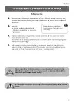
General view of frame is represented in Fig. 1. Mount details in such a way 

to make side shelves facing coverage. Assemble the frame from numbered 

elements.

Legend:

 - arrow indicates installation 

direction according to manuals’ 

schemes

Connect elements using profi les, screws and nuts. In this case, no matter 

what element is on top.

Be careful not to damage elements, because they don’t have enough rigidity 

before fi nal assembling. 

Use supports (for example, chairs) on temporary stages of installation for 

uniform lifting of frame assembled. To coincide holes in complicated joints 

use a nail of 5 mm diameter or a drift pin with tapered end.

1.

2.

3.

4.

Some elements have free 

holes resulted from elements’ 

uniformity.

Introduction

Be careful! Elements have sharp angles. Guard against cutting. Work in safety 

gloves.

When assembling the frame, connect elements using all available holes. 

Simplifi ed connection with one or two screws is a violation of installation 

rules and a ground for warranty waiver.

Summary of Contents for PREMIUM

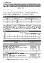
Page 1: ...DACHNAYA STRELKA 3 any length multiple to 2 m width 3 0 m height 2 4 m cellular polycarbonate greenhouse Technical certificate Installation manual page 2 6 page 7 22 www serrashop it PREMIUM...

Page 2: ...limate favorable for growing garden crops on cottage and household plots Area of covered soil depends on length of the greenhouse table 1 Height of installed frame is 2 4 m width is 3 0 m The greenhou...

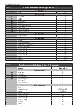
Page 3: ...trut liner 2 13 horizontal door element 6 16 end cover plate 2 17 door cover plate for rotator 4 18 stiffening boom 2 21 middle strainer 4 left tubular reinforcing element 2 right tubular reinforcing...

Page 4: ...plate 2 bottom wire bandage 4 top wire bandage 2 screw M5x10 150 screw M5x14 4 screw M5x35 16 screw M5x50 4 nut 174 washer 16 Table 5 Small window detailed parts list 7th package Name Quantity 1st pa...

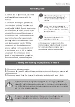
Page 5: ...rub surface of polycarbonate sheets with a brush metalized fabric or other abrasive materials 2 In winter coverage of greenhouse should not be removed provided that snow load is limited Should greenho...

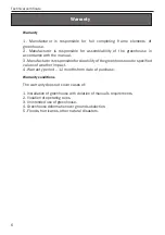
Page 6: ...rranty conditions The warranty does not cover cases of 1 Installation of greenhouse with violation of manual s requirements 2 Violation of operating rules 3 Unintended use of greenhouse 4 Greenhouse d...

Page 7: ...they don t have enough rigidity before final assembling Use supports for example chairs on temporary stages of installation for uniform lifting of frame assembled To coincide holes in complicated joi...

Page 8: ...rame inside view outside view 4 angle angle 4 2 2 4 6 2 1 arm 4 outside view 4 5 arm 7 1 6 6 inside view 4 2 3 1 Fig 1 outside view inside view arm 2 2 2 2 2 2 2 2 2 2 2 2 4 4 4 4 8 8 5 6 6 7 7 6 10 1...

Page 9: ...hnaya Strelka 3 extended by any number of inserts Fig 2 Fig 3 858 4060 1000 1000 1000 1000 3000 Greenhouse foundation support layout plan Fig 4 1071 60 21 General view of Vstavka insert for Dachnaya S...

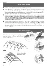
Page 10: ...use Install greenhouse in accordance with photographs of installation stages and units represented in Fig 5 12 The figures show installation of greenhouse of 4 m length Required length is reached usin...

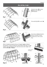
Page 11: ...6 6 7 8 21 Fig 10 2 6 4 2 1 arm 6 Fig 7 Connect arcs 4 to arcs 4 from one side of greenhouse Connect balks 2 to arcs 4 Fig 9 Connect arcs 4 and balks 2 from the other side of greenhouse in the same w...

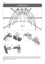
Page 12: ...h arc inside of greenhouse frame Assemble side brace assembled from two elements 10 Mount side brace liner 11 on the joint of elements 10 and connect it to arc 4 9 9 18 18 10 4 10 2 2 Assembling stage...

Page 13: ...ed door and end small window Assemble door and end small window from elements 12 13 14 15 Fig 12 14 14 14 12 12 12 12 12 13 15 15 15 15 19 19 20 20 14 15 Fig 12 12 13 14 13 13 13 13 15 15 14 14 14 12...

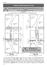
Page 14: ...RDANCE WITH Fig 13 or 13 Fig 14 2100 x 600 mm cellular polycarbonate sheet Fig 13 Vertical position of cellular on ridge panel Fig 13 Horizontal position of cellular on ridge panel 6000 Door Door Smal...

Page 15: ...sheet film is clear After marking the sheet but before its cutting make marks on protective side of each piece of sheet after removal of transport film sheet sides have no visual differences Transpor...

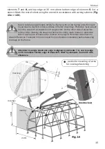
Page 16: ...hers by elements 6 7 8 21 and by angles using tap screws with washers Holes for screws are drilled by boring bit of 5 mm diameter from inside of greenhouse through holes in frame elements Mount top pi...

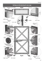
Page 17: ...aler hinge sealer coverage coverage coverage 17 screw 5 14 handle handle coverage adhesive tape door sealer hinge adhesive tape door sealer hinge sealer coverage door sealer door sealer coverage hinge...

Page 18: ...8 screw 5 35 screw 5 35 door coverage small window coverage door coverage ridge panel element 16 screw 5 50 screw 5 35 element 5 door sealer door sealer door sealer element 19 element 19 element 13 el...

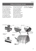
Page 19: ...end washers and hooks in accordance with Fig 24 Fig 24 washer washer hook end coverage angle angle screw 4 10 screw 5 35 ground level 16 2 8 Install tubular reinforcing elements of door opening in acc...

Page 20: ...sitioning protective layer outside Eliminate mismatch of edges after cutting halves and putting them together by cutting of outstanding edge If edges outstanding cutting error exceeds 5 mm level both...

Page 21: ...ssentially nonparallel to the frame arc edges it means that the frame is not leveled before screw tightening and this operation should be repeated Prepare next sheets of polycarbonate in a similar way...

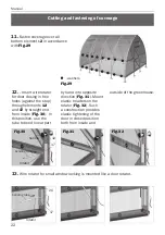
Page 22: ...ht end from inside Fig 30 In this position use the tube to bend linear part by hand into opposite direction Fig 31 Mount elastic headers on the rotator Fig 32 Such a construction provides elastic tigh...

Reviews: