background image

 Product User Guide  |  5

UltraShock

DEVICE OPERATION

Connecting and Starting the Data Logger

1.  Once the software is installed and running, plug the 

interface cable into the data logger.

2.  Connect the USB end of the interface cable into an 

open USB port on the computer.

3.  The device will appear in the Connected Devices list, 

highlight the desired data logger.

4.  For most applications, select Custom Start from the 

menu bar and choose the desired start method, 
reading rate and other parameters appropriate for the 
data logging application and click Start. (Quick Start 
applies the most recent custom start options, Batch 
Start is used for managing multiple loggers at once, 
Real Time Start stores the dataset as it records while 
connected to the logger.)

5.  The status of the device will change to Running or 

Waiting to Start, depending upon your start method.

6.  Disconnect the data logger from the interface cable and 

place it in the environment to measure.

Note:

 The device will stop recording data when the end of memory 

is reached or the device is stopped. At this point the device cannot be 
restarted until it has been re-armed by the computer.

Downloading Data from a Data Logger

1.  Connect the logger to the interface cable.
2.  Highlight the data logger in the Connected Devices list. 

Click 

Stop

 on the menu bar.

3.  Once the data logger is stopped, with the logger 

highlighted, click 

Download

. You will be prompted to 

name your report.

4.  Downloading will offload and save all the recorded 

data to the PC.

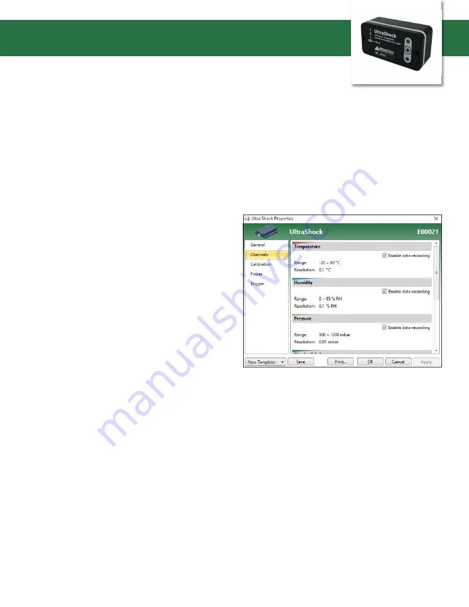
Enabling and Disabling of Channels

1.  Connect the logger to the interface cable.
2.  Highlight the data logger in the Connected Devices list. 
3.  Click 

Properties

 or right click the logger in the list and 

select 

Properties

.

4.  Select 

Channels

 in the Properties list.

5.  Check or uncheck 

Enable data recording

 for each 

channel you want to enable or disable.

Summary of Contents for UltraShock

Page 1: ...ck Data Logger PRODUCT USER GUIDE TABLE OF CONTENTS 2 Product Overview 4 Software Installation Guide 5 Device Operation 8 Product Maintenance 9 Specifications 10 Dimensional Drawings To view the full...

Page 2: ...occur when the UltraShock is mounted by two bolts directly to a solid metal flat surfaced object of significant mass For various applications the rigid bolted down mounting may not be optimal or prac...

Page 3: ...SB connected and adequate battery charge level Flashes every 15 seconds maximum Indicates low battery charge level Logging Data with USB communication Flashes every 15 seconds Indicates normal operati...

Page 4: ...ts before other parameters Pressure The UltraShock pressure sensor is designed to measure barometric pressure from very low altitudes to those altitudes found in aircraft up to high altitude balloons...

Page 5: ...pending upon your start method 6 Disconnect the data logger from the interface cable and place it in the environment to measure Note The device will stop recording data when the end of memory is reach...

Page 6: ...s will only sample data at the logging rate For instance if a 30 second logging rate was selected then only a single data point is captured at each 30 second instant The potential to lose valuable dat...

Page 7: ...100 samples are acquired at the selected logging rate The trigger sample count should be chosen carefully because it may gather data points for which we have no interest For instance if 100 were enter...

Page 8: ...cell pack Please note the safe handling and storage recommendations in the specifications section Inspection The UltraShock may be inspected visually for any signs of damage especially to the gray gas...

Page 9: ...nto the device to restrict access to configuration options Data may be read out with the password Calibration Digital calibration through software Calibration Date Automatically recorded within device...

Page 10: ...21 8 mm 1 72 43 7 mm 0 20 5 1 mm 2X 0 20 5 1 mm THRU 4X R0 25 R6 4 mm APPLIQUE COVER GASKET BATTERY PACK RH AND PRESSURE SENSOR PORT TYPE C USB CONNECTOR 3 00 76 2 mm RED LED INDICATOR GREEN LED INDIC...

Reviews: