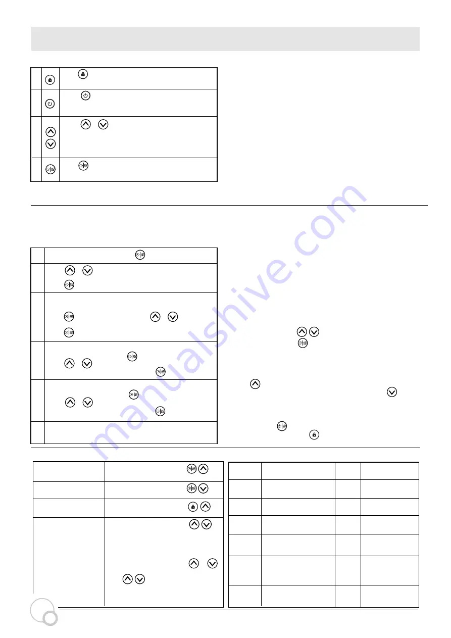
continue SETTING AND OPERATION
5.4 Running Capacity Setting
5.5 Timer mode
The pump’s on/off and running capacity could be commanded
by timer, which could be programmed daily as needed.
Maximum 4 timers can be set on the control panel.
Enter timer setting by pressing .
Press or to set the local time.
When enter the timer-1 setting, the timer indicator 1
will light up. “StA”will be shown on the screen.
Press to proceed and then press or to set the
start time of timer-1 (with 30 minutes for each step),
press to con
fi
rm.
Press to confirm and move to timer-1
When the start time of timer 1 is con
fi
rmed, “End”will be
shown on the screen. Press to proceed and then
press or to set the end time of timer-1
(with 30 minutes for each step), press to con
fi
rm.
When the end time of timer 1 is con
fi
rmed, “SPd”will be
shown on the screen. Press to proceed and then
press or to set the running capacity of timer-1
(30% - 100%, each step by 5%), press to con
fi
rm.
When the timer 1 setting is completed, repeat steps 3 – 5
to complete the setting of timer 2 – 4.
Hold for more than 3 seconds to read the
real-time power.
Press or to set the running
capacity between
30%~100%, each step by 5%.
Press to start. The pump will run at 80% of the
running capacity at the initial startup after the
self-priming.
NOTE:
When timer mode is acti
v
ated, if the set time period contains the
current time, the pump will start running according to the set running
capacity and the corresponding timer indicator (1 or 2 or 3 or 4) will
stay on, and the set running capacity will be shown on the screen.
If the set time period does not contain the current time, the timer
indicator (1 or 2 or 3 or 4) that isabout to start running will light up
and flash, and the current time will be shown on the screen.
All 4 time periods should be set in chronological order.
O
v
erlap setting of time will be considered in
v
alid, the pump will only
run based on the pre
v
ious
v
alid setting.
During the timer setting, if users want to return to the pre
v
ious
setting item, hold both for 3 seconds. If users don’t need
4 timers, they can hold for 3 seconds after completing the
setting of the speci
fi
c timer, the system will automatically sa
v
e the
current set
v
alue and acti
v
ate the timer mode.
When the timer mode is on, users can check the setting of each timer.
Press to select the speci
fi
c timer (1 or 2 or 3 or 4), and the
corresponding timer indicator will light up. Then press to check
the start time, end time, and running capacity setting of the
selected timer.
Users can hold for 3 seconds to read the real-time power and
exit timer mode by holding for 3 seconds.
2
3
4
1
2
3
4
5
6
Hold for more than 3 seconds to unlock the
screen.
1
Note:
a. When the running capacity is adjusted, the system will sa
v
e the
latest parameter automatically.
b.When setting 100% speed, the pump will increase the speed
automatically if the pipeline resistance is high, but will not exceed
the rated power of each model.
5.6 Parameter Setting
Description
Default
Setting Setting Range
1
100%
2
80%
3
40%
4
100%
5
25
Restore factory setting.
Under off mode, hold both for
3 seconds.
Check the software
v
ersion.
Under off mode, hold both for
3 seconds.
Manual priming.
Enable or disable the
priming that occurs at
start.
Backwash
capacity
25:enables
0:disables
80~100%, by 5%
increments
30~100%, by 5%
increments
30~100%, by 5%
increments
30~100%, by 5%
increments
Under ON mode, hold both for
3 seconds.
Enter parameter
setting as shown.
Under OFF mode, hold both
for 3 seconds to enter the parameter
setting. The parameter address
(on the left) and default setting
v
alue
(on the right) will flash alternately on
the screen. Users can press or
to adjust the current
v
alue, and hold
both for 3 seconds to the next
parameter address. It will exit the
parameter setting after 10 seconds
without operation.
Parameter
Address
6
INVER
FLOW
Self-priming/
2min
6
Self-primming
recheck time
1-15min by 1min
increments
Digital input 2
Digital input 3
Digital input 4
For the purpose of
backwashing, users can set a high running capacity
according to the size of filter.
Summary of Contents for invermac inverFLOW INVFLO300
Page 1: ...Powered by INSTALLATION MANUAL...
Page 12: ...AG045 DE 05...


