6-18
6. MODE SETTING OF THE TRANSMITTER
This device provides the
“A MODE” in which the initial values of the Transmitter are established, the
“OUTRIGGER MODE” in which the outriggers are set or stowed, and the “CRANE MODE” where the
Crane is operated. This device is designed to switch to the applicable mode for the operation by the
Transmitter.
6.1 A MODE
•To perform A Mode setting, turn ON the starter switch in the machine body first, set the
Travelling lever stand to "Crane Operation" Position next, then turn ON the main switch of the
Receiver.
• Before the setting of values for A MODE, ensure that “A MODE” is correctly indicated in the
LCD screen. Otherwise, un-expected motion of the Crane may result in a serious accident, due
to entry of values in the other mode, by mistake.
6.1.1 OPENING A MODE SCREEN
Push the Speed/Mode button and Power switch jointly for 2
seconds. A message as “A MODE” appears in the LCD screen for
2 seconds.
6.1.2 MESSAGES IN THE A MODE SCREEN
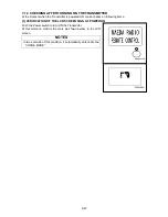
Refer to the figure on the right for the A MODE screen:
It contains eight function items ((1) to (8)) and the Exit command
((9)).
NOTES
In the A MODE, following applicable items are adjustable, as
required:
(1)
“Contrast ratio” of LCD screen
(2)
“Loudness control”
(3)
The “Engine speed limit”, controllable by the Accelerator
lever.
(4)
LCD backlight, “Time for lighting, until the auto-cut”.
(5)
“Auto Shut-OFF time” of the Transmitter power.
(6)
“Low idling rate” of the engine. (Idling only while the crane
operation levers are manipulated.)
(7)
Reset of “user values” by the speed set-up mode.
(8)Version information of the Transmitter hardware.
To switch the function item to another, or to change the setting
value of the function, use the Hook raising and lowering lever.
Then, to fix the value in the function, push the Setting button.
Summary of Contents for MC-174CRM
Page 2: ......
Page 8: ...0 6...
Page 60: ...2 38 31 Precautions for use portable card 101 2141000...
Page 62: ...2 40...
Page 77: ...3 15...
Page 117: ...3 55 5 Push the choke knob forward to return the original position...
Page 195: ...4 23...
Page 197: ...4 25...
Page 214: ...5 4 2 OVERALL DIMENSIONS...
Page 215: ...5 5 3 OUTRIGGER SPREAD DIMENSIONS...
Page 219: ...5 9 5 WORKING RANGE...
Page 220: ...5 10...


