background image


V1.0 

– Feb-12 

User’s Manual 

Page 7 of 35 


1.2 Characteristics Overview 

The module’s most important characteristics are:  
 

  A2200-A 

o

  Operable at 3.3V / 41mA  @ 1 fix per second 

o

  UART interface at 3.3V CMOS level 

o

  Prepared for SPI Slave support at 3.3V CMOS 

  Direct passive antenna support 

  Switched antenna voltage for active antenna support 

  Small form factor of 10.2 mm x 14 mm (0.40

” x 0.55”)  

  Supported temperature range: -40°C to +85°C 

  Single-sided SMT component, for reflow soldering 

  Tape & reel packaging 

 
The A2200-A receiver module is available as off-the-shelf components, 100% tested 
and shipped in standard tape-and-reel package. 
 

1.3 RoHS and Lead-Free Information 

Maestro

’s products  marked  with  the  lead-free  symbol  either on the module or the 

packaging  comply  with  the  "Directive  2002/95/EC  of  the  European  Parliament  
and  the  Council  on  the  Restriction  of  Use  of  certain  Hazardous  Substances  in  
Electrical  and  Electronic  Equipment"  (RoHS). 


All Maestro GPS receiver modules, smart GPS antenna modules and telematics 
units are RoHS compliant. 


Summary of Contents for A2200-A

Page 1: ...GPS Receivers A2200 A A Description of Maestro s GPS Receiver Module A2200 A User Manual Version 1 0 ...

Page 2: ...escription 0 1 07 11 11 First draft based on A2200 1 0 12 12 11 Updated photo Pin out Information Packing mm dd yy Name Date Signature Written by Happy wen 12 12 11 H W Checked by Sam Law Wallace Lee 12 12 11 S L W L Approval by Frank Tang Calvin Yau 12 12 11 F T C Y ...

Page 3: ...D FOR USE IN LIFE SUPPORT DEVICES OR SYSTEMS WITHOUT THE EXPRESS WRITTEN APPROVAL OF MAESTRO THIS DOCUMENT MAY PROVIDE LINKS TO OTHER WORLD WIDE WEB SITES OR RESOURCES BECAUSE MAESTRO HAS NO CONTROL OVER SUCH SITES AND RESOURCES MAESTRO SHALL NOT BE RESPONSIBLE FOR THE AVAILABILITY OF SUCH EXTERNAL SITES OR RESOURCES AND DOES NOT ENDORSE AND IS NOT RESPONSIBLE OR LIABLE FOR ANY CONTENT ADVERTISING...

Page 4: ...2 Active Antennas 15 3 3 Serial Port Settings 16 3 4 Improved TTFF 16 4 Mechanical Outline 17 4 1 Details Component Side A2200 A 17 4 2 Details Solder Side A2200 A 18 5 Pin out Information 19 5 1 Layout A2200 A 19 5 2 Description A2200 A Signals 20 6 Electrical Characteristics 21 6 1 Operating Conditions 21 6 2 Absolute Maximum Ratings 21 6 3 DC Electrical Characteristics 22 7 Mounting 23 7 1 Prop...

Page 5: ...RFawareTM Support 28 10 4 Push to Fix Mode 28 10 5 Hibernate Mode 29 10 6 Extended Ephemeris 29 10 7 Antenna Status Adaptation 30 10 7 1 Antenna Sensor 30 10 7 2 Antenna Sensor with Current Limiter 31 10 8 VANT Pin 32 11 Evaluation Kit EVA2200 A 33 12 Related Information 34 12 1 Contact 34 12 2 Related Documents 34 12 3 Related Tools 34 13 List of Figures 35 14 List of Tables 35 ...

Page 6: ...d time information The A2200 A is a module designed for a 3 3V environment 1 1 Feature Overview The A2200 A is new module with the following outstanding features Fast responsive location experience o High sensitive navigation engine with tracking down to 163dBm o 48 track verification channels o SBAS WAAS EGNOS MSAS GAGAN Breakthrough micro power technology o Requires only 50 500µA to maintain hot...

Page 7: ... C to 85 C Single sided SMT component for reflow soldering Tape reel packaging The A2200 A receiver module is available as off the shelf components 100 tested and shipped in standard tape and reel package 1 3 RoHS and Lead Free Information Maestro s products marked with the lead free symbol either on the module or the packaging comply with the Directive 2002 95 EC of the European Parliament and th...

Page 8: ...ase hardware release factory code year week of assembly and a 6 digit serial number Representing Factory code Product Number Part Number Software Release Hardware Release Assembly Year Week Serial Number Number of digits 25 XX XXXXXXX XXXX XX XX XXXX XXXXXX 2 6 4 2 2 4 6 Example GS A2200A 9322 01 01 1126 000005 Meaning GSL Given Given Given Given Year 11 Week 26 Increment from 000001 up to 999999 ...

Page 9: ...2 The calibrated clock of the receiver has not stopped thus it knows precise time to the µs level 3 The receiver has estimates of time date position and valid almanac and ephemeris data 4 The receiver has estimates of time date position and recent almanac 5 The receiver has no estimate of time date position and no recent almanac Note Performance sensitivity and TTFF might slightly decrease below 3...

Page 10: ... The order number is built as follows A2200 Axxxx A2200 A is the model name The xxxx refers to the current part number on the module 2 2 Packing of the A2200 A The A2200 A GPS module come in a tape and reel package suitable for pick and place machines Figure 2 A2200 A tape specifications 1 ...

Page 11: ...ions 3 One complete reel holds 1300 pcs A2200 A modules There are 2 kinds of packaging for shipment A One box holds 1 reel Reel diameter 33 cm Inner box dimensions 36 W x 36 L x 4 5 H cm Box dimensions 38 8 W x 38 8 L x 5 7 H cm Gross weight 2 58 Kg Net weight 0 78 Kg B One box holds 3 reels Reel diameter 33 cm ...

Page 12: ...V1 0 Feb 12 User s Manual Page 12 of 35 Inner box dimensions 36 W x 36 L x 4 5 H cm Outer box dimensions 38 W x 38 L x 16 H cm Gross weight 4 92 Kg Net weight 2 34 Kg ...

Page 13: ...anual Page 13 of 35 2 3 Additional Equipment EVA2200 A Evaluation Kit including one module A2200 A Table 3 Additional equipment A detailed description of the EVA2200 A Evaluation Kit can be found in the appro priate manual ...

Page 14: ...ll the GPIO up right after reset by other means NOTE 2 The ON_OFF input of the A2200 A needs to be connected to a push pull output of a microprocessor For a wake up including the initial one after power on a LOW HIGH transmission is mandatory NOTE 3 It is recommended to connect the nRST pin of the A2200 A to an open collector open drain output of a microprocessor 3 1 Minimum Configuration The foll...

Page 15: ...2 For capacity values see datasheet of actual component used Use 3 3V level shifter MAX3232 or equivalent External antenna input impedance is 50 Match as close as possible 3 2 Antennas Generally the quality of the GPS antenna chosen passive or active is of paramount importance for the overall sensitivity of the GPS system Losses through a bad an tenna long cables or tracks or a bad antenna positio...

Page 16: ...y the external pull up resistor as outlined in Minimum Configuration the default settings are NMEA 4800 baud 8 data bits no parity 1 stop bit no flow control 3 4 Improved TTFF In order to improve the TTFF Time To First Fix it is recommended to keep Vcc supplied at all times This will allow taking advantage of sophisticated low power mode features of the SiRFstarIV ROM chip set ...

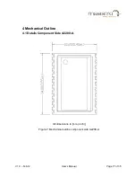
Page 17: ...V1 0 Feb 12 User s Manual Page 17 of 35 4 Mechanical Outline 4 1 Details Component Side A2200 A All dimensions in mm inch Figure 7 Mechanical outline component side A2200 A ...

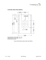
Page 18: ...eb 12 User s Manual Page 18 of 35 4 2 Details Solder Side A2200 A Solder pad size outer pads 1 0 x 0 8 Solder pad size inner pads 1 2 x 1 2 All dimensions in mm Figure 8 Mechanical outline solder side A2200 A ...

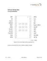
Page 19: ...1 0 Feb 12 User s Manual Page 19 of 35 5 Pin out Information 5 1 Layout A2200 A Pin 1 marker Figure 9 Pin out information bottom view A2200 A Center Ground pins are for shock vibration resistance purpose ...

Page 20: ...ply Ground power supply 9 VANT Antenna Supply Voltage Input Power supply input for external active antenna provide ac cording voltage up to 5 0 VDC switched internally 10 ANT_GND RF GND Antenna Ground 11 ANT_IN Antenna Input Antenna signal Z 50 Ohm antenna input must not exceed 30dB gain including cable loss 12 GPIO3 Input Output Leave open 13 ExtInt Input Output Interrupt input for MEMS interface...

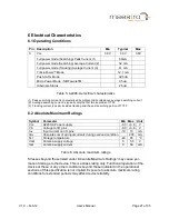
Page 21: ...ent typically includes tracking and the post searching portion of TTFF 6 2 Absolute Maximum Ratings Symbol Parameter Min Max Unit Vcc A2200 A Power supply 0 3 3 6 V Vin Voltage to I O pins 0 3 3 6 V Iov Input current on I O pins 10 10 mA Itdv Absolute sum of all input currents during overload condition 200 mA Tst Storage temperature 40 85 C Vant Antenna supply voltage 0 5 5 V Iant Antenna supply c...

Page 22: ...rical Characteristics Symbol Parameter Min Max Unit TX0 WAKEUP Voh 4mA 2 6 Vcc V Vol 4mA 0 45 V RX0 Vih 2 0 Vcc V Vil 0 8 V nRST for safe reset 0 2 V ON_OFF Vih 1 35 Vcc V Vil 0 3 0 45 V BOOTSEL Vih 1 35 2 2 V Table 7 DC electrical characteristic A2200 A ...

Page 23: ...dule in convection or IR convection ovens are as follows according to IPC JEDEC J STD 020D Parameter Value Peak temperature RoHS compliant process 245 C Average ramp up rate to peak 217 C to Peak 3 C second max Preheat temperature min 150 C max 200 C Ramp up time from min to max preheat temperature 60 120 seconds Temperature maintained above 217 C 60 150 seconds Time within 5 C of actual peak temp...

Page 24: ...e routed to the ground plane of the PCB the ground plane is on a lower PCB layer by vias as demonstrated in the drawing Figure 10 Antenna connector strip line A2200 A In order to achieve the impedance of 50 the width of the strip line needs to be calculated It depends on the thickness or height of the PCB layer both parameters are shown in following drawing For the calculation it is assumed that t...

Page 25: ...V1 0 Feb 12 User s Manual Page 25 of 35 In this case the width should be about 1 8 times the height of the PCB W 1 8 x H In the example one would get a width of W 1 8 x 0 8 mm 1 44 mm ...

Page 26: ...ntenna specification Limitations Supply voltage voltage fed into VANT pin 5V max Supply current 50mA max Recommendations Gain 15dB should not exceed 20 dB including cable loss Noise figure 1 5dB The recommendations apply to the majority of active antennas that can be found in the market Anyhow the quality of the GPS antenna chosen is of paramount im portance for the overall sensitivity of the GPS ...

Page 27: ...oned according to EIA JEDEC standard JESD22 A113 B Level 3 Basic qualification tests MSL Classification according to J STD 020C MSL3 245 C MSL Rework Compatibility according to J STD 020C Temperature Cycling 40 C 85 C Temperature Humidity Bias 70 C 85 RH Low High Temperature Operating 40 C 85 C High Temperature Operating Life 85 C Vibration Variable Frequency Mechanical Shock Please contact Maestr...

Page 28: ...ng messages either in NMEA or OSP mode The shutdown is completed after maximum 1s Therefore the module should be supplied with voltage for that time after the shutdown sequence was initiated 10 3 SiRFawareTM Support SiRFawareTM is a low power operating mode that seeks to maintain low uncertainty in position time and frequency and to maintain valid current Ephemeris using either data collected from...

Page 29: ...ng the ON_OFF pin is neces sary 100ms pulse width 10 6 Extended Ephemeris The receiver is capable of supporting two versions of using Extended Ephemeris EE data The first one is the version where the EE data are calculated on a server are transmitted to device incorporating the receiver and are then loaded into the receiver These data can be valid for up to seven days The second version is the int...

Page 30: ...16mA 10 7 1 Antenna Sensor The following circuit is a proposal on how you can feed an antenna with 3 3V and provide an output for the ANTSTAT pin The value of the components may need an adaptation in the final application For example the input current of the chosen comparator goes into that equation The thresholds defined in this circuit are quite close to the ones described above Their value is d...

Page 31: ...s as above apply We strongly recommend simulating and testing the GPS receiver integrated in your product design before implementing the finalized product in the appropriate market ap plication In any case it is the responsibility of the designer to test and verify the implementation Figure 13 Application note Antenna sensor adaptation with current limiter Current Limiter ...

Page 32: ...s 50 mA Note Shortcut between ANT and GND may damage the A2200 A GPS receiver module This should be avoided by using an antenna current limiter The circuit chapter 10 7 2 Antenna Sensor with Current Limiter works for Vcc from 3V to 5V The antenna current will be limited to 50 mA approximately If other transistors are used other resistor values may be necessary as well We strongly recommend simulat...

Page 33: ...interface is an extension of the serial port 0 therefore sending NMEA sentences or binary information and accepting commands At the same time it provides power to the module Accompanied by both an active and passive antenna it offers a ready to go set For the development of new software and applications the Evaluation Kit also provides NMEA and binary messages on CMOS level via a terminal plug Fig...

Page 34: ...zations and comments or proposals to Maestro Hongkong for further improvements are highly appreciated Maestro Wireless Solutions Limited Address Unit 3603 09 36 F 118 Connaught Road West HK Main Line 852 28690688 Fax 852 25254701 support gps maestro wireless com www maestro wireless com 12 2 Related Documents GPS Evaluation Kit EVA2200 A Maestro GSD4e NMEA Manual SiRF GSD4e OSP Manual SiRF 12 3 Re...

Page 35: ...ttom view A2200 A 19 Figure 10 Antenna connector strip line A2200 A 24 Figure 11 Strip line parameters A2200 A 24 Figure 12 Application note Antenna sensor adaptation 30 Figure 13 Application note Antenna sensor adaptation with current limiter 31 Figure 14 Evaluation kit EVA2200 A 33 14 List of Tables Table 1 A2200 A GPS characteristics 9 Table 2 A2200 A dimensions and weight 9 Table 3 Additional ...

Reviews: