Chapter 11
Input/Output port control
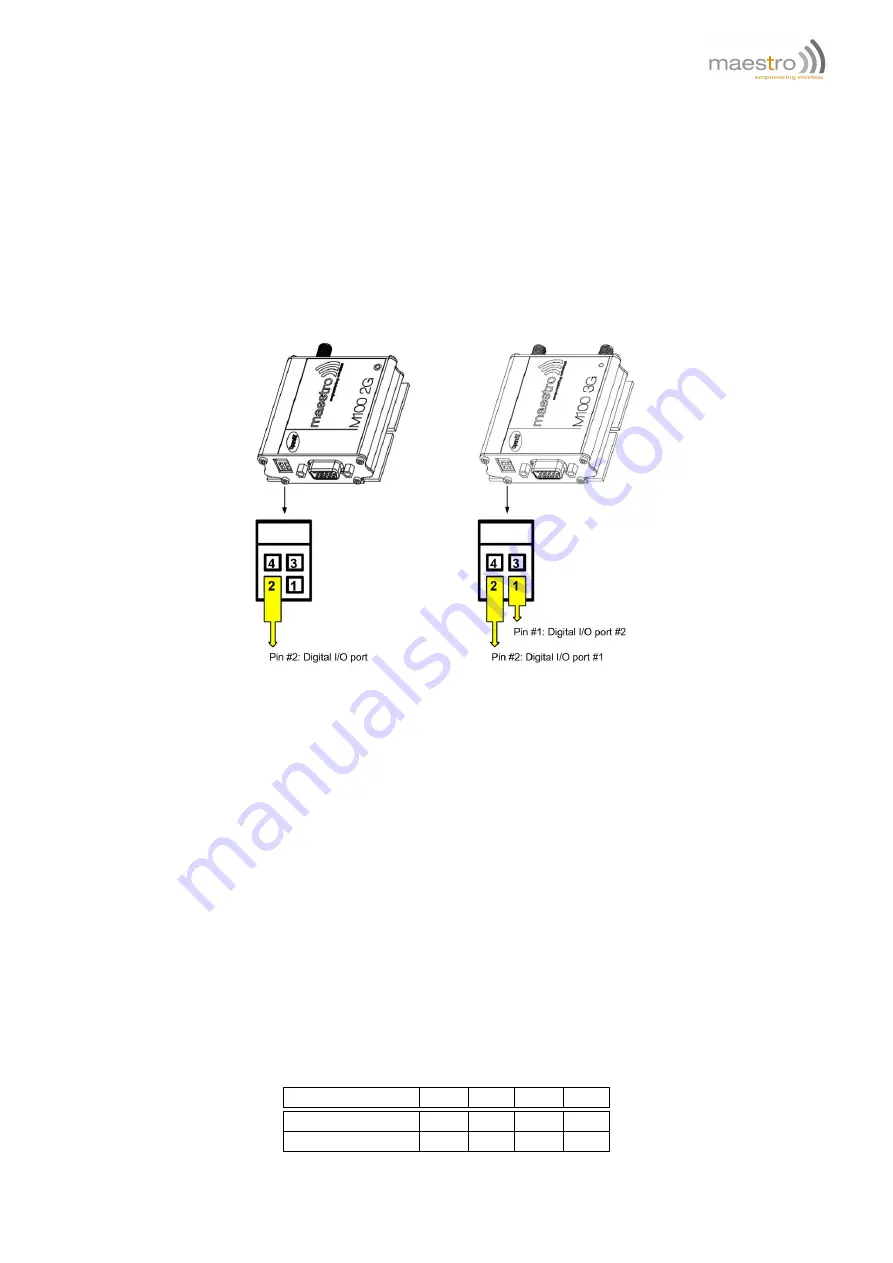
M100 3G is equipped with two I/O ports on the power connector. Each port is connected to an input and output pin
inside.
The SmartPack supports I/O port function with two sets of AT commands:
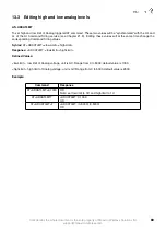
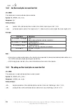
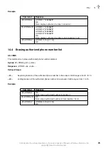
1. I/O board control commands (originally from Heritage modem I/O expansion plug-in): +IOBR, +IOBW, +IOBOR.
Those commands control the two I/O ports functions both input and output.
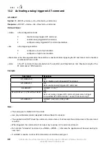
2. I/O port triggered AT commands (AT+IOAT, originally from earlier M100/M100evo). This command use the I/O
port #1 as a sensor. If the input matches the condition a specified AT command will be executed.
Both commands can be used at the same time. And some settings are shared by both (see below).
11.1
Relationship between input and output of I/O ports
Please refer to M100 3G user guide for the electrical connection method for input or output applications.
Each port is connected to an input and output pin inside modem. However an external DC voltage signal MUST be
applied in order to use I/O ports. Output pin can be set to On (1) or Off (0) by AT command. Input pin can be read by
AT command as either high (1) or low (0).
Following table list the relationship between external DC input, input and output pin:
External DC input
High
Low
High
Low
Output setting
1
0
0
1
Input reading
1
1
0
1
Confidential, the whole document is the sole property of Maestro Wireless Solutions ltd.
support@maestro-wireless.com
59


