background image

TDC series user manual rev 1.0

15

M

A

G

 T

H

E

A

TR

O

N

4.3. AC Mains supply

The AC Main connection is made via the IEC C13 

connector.

Connection to the main shall be 

done only by an electrotechni-

caly skilled person according to 

the national requirements of the 

countries where the unit is sold.

Make sure the AC mains volt-

age used is within the accept-

able operating voltage range: 

115V-230V ±10%.

It is important to connect the 

ground for safety, do not use 

an adapter that disables the 

ground connection.

The TDC series amplifiers have an automatic power 

factor correction system - PFC - for a perfect mains 

network interface. The PFC minimizes the reactive 

power reflected on the network and reduces the 

harmonic distortion on voltage/current waveform: 

in this way, the amplifier is seen as a resistive load 

from the mains network. Furthermore, the system 

allows performance to be maintained even in case of 

varying mains voltage.

4.4. Precautions regarding installation

Placing and using the amplifier for long periods on 

heat-generating sources will affect its performance. 

Avoid placing the amplifier on heat-generating 

sources. Install this amplifier as far as possible from 

tuners and TV sets. An amplifier installed close to 

such equipment may experience noise or generic 

performance degradation.

WARNING: TO PREVENT FIRE OR ELECTRIC 

SHOCK:

- This device must be powered exclusively by earth-

connected mains sockets in electrical networks 

compliant with the IEC 364 or similar rules.

- Install the amplifier into a rack cabinet.

- With a TDC amplifier, a sectioning breaker between 

the mains connections and the amplifier must be 

installed inside the rack cabinet. The suggested 

device for TDC-1200W and TDC-3200W is 10A class 

C or D.

- Before powering this amplifier, verify that the 

correct voltage rating is being used.

- Verify that your mains connection is capable of 

satisfying the power ratings of the device.

- Do not use this amplifier if the electrical power cord 

is frayed or broken.

- Output terminals are hazardous: wiring connections 

to these terminals require installation by an instructed 

person.

- Take care to secure the output terminal before 

switching the device on.

- Take care to secure the output terminal before 

switching the device on.

- To avoid electrical shock, do not touch any exposed 

speaker wiring while the amplifier is operating.

- Do not spill water or other liquids into or on the 

amplifier.

- No naked flame sources such as lighted candles 

should be placed on the amplifier.

- Do not remove the cover. Failing to do so will expose 

you to potentially dangerous voltage.

- It is necessary to verify these fundamental 

requirements of safety and, in case of doubt, require 

an accurate check by qualified personnel.

- The manufacturer cannot be held responsible for 

damages caused to persons, things, or data due to 

an improper or missing ground connection.

- Contact the authorized service center for ordinary 

and extraordinary maintenance.

IN

STA

LL

AT

IO

N

Summary of Contents for TDC Series

Page 1: ...Power amplifiers TDC series User manual TDC 1200W TDC 3200W Models THEATRON...

Page 2: ...Menu diagram 18 7 2 Event screen 18 7 3 AMPLIFIER MENU 18 7 3 1 AMP SETTINGS submenu 18 7 3 2 METERS submenu 18 7 3 3 INFO submenu 18 7 3 4 NETWORK submenu 19 7 3 5 SIGNAL GENERATOR submenu 19 7 3 6...

Page 3: ...TDC series user manual rev 1 0 3 MAG THEATRON Panel A Dimensions DIMENSIONS...

Page 4: ...dio controls 6 band parametric EQ volume polarity delay DSP utility controls Power saving mode power up mode Input sensitivity 5dBu 7dBu Maximum input level 20dBu Input impedance 18 kOhm unbal 36 kOhm...

Page 5: ...button 1 Mains switch 2 Mains plug 3 Output Phoenix connector 4 Channel 1 unbalanced RCA input 5 Channel 2 unbalanced RCA input 6 Channel 1 balanced XLR female input connector 7 Channel 2 balanced XL...

Page 6: ...1 0 6 MAG THEATRON Panel D Audio and Ethernet connection Input connectors unbalanced Ch1 Ch2 shield Ch1 shield Ch2 Input connectors balanced shield 2 3 1 Through connectors balanced shield 2 3 1 AUDI...

Page 7: ...EN WHITE 2 ETH TX GREEN 3 ETH RX ORANGE WHITE 4 not connected BLUE 5 not connected BLUE WHITE 6 ETH RX ORANGE 7 not connected BROWN WHITE 8 not connected BROWN 568A 568B Loudspeaker connection bridged...

Page 8: ...ress to return to the AMPLIFIER menu simultaneous pressing the button 1 and the 2 button for controlling two channels Turn to display the AMPLIFY menu or use to edit the parameters for DSP menu if not...

Page 9: ...rname Channel 2 Edit the unit name Selection Name Standart names 3 Selection Name Range 19 25 if present Ethernet module 4 Network Amplifier identifier editor 4 1 Exit Save Amplifier menu 16 Ohm 1 Ohm...

Page 10: ...TDC series user manual rev 1 0 10 MAG THEATRON...

Page 11: ...SONNEL FOLLOWING APPLICABLE SAFETY RULES DO NOT ALLOW INSTALLATION OF THIS UNIT IF INSTALLATION HARDWARE IS BROKEN BENT PARTS ARE MISSING OR IS OTHERWISE DAMAGED The triangle with the lightning bolt i...

Page 12: ...user is encouraged to try to correct the interference by one or more of the following measures Reorient or relocate the receiving antenna Increase the separation between the equipment and receiver Con...

Page 13: ...ques and adds advanced DSP and controls so projects are more streamlined with reduced total costs Efficient class D amplification provides for less environmental footprint and along with smart standby...

Page 14: ...he temperature detected by the sensors rises over carefully predetermined values This ensures that fan noise and internal dust accumulation are kept to a strict minimum Shouldhowevertheamplifierbesubj...

Page 15: ...sively by earth connected mains sockets in electrical networks compliant with the IEC 364 or similar rules Install the amplifier into a rack cabinet With a TDC amplifier a sectioning breaker between t...

Page 16: ...log inputs are provided with two RCA connectors Refer to panel D for proper RCA pinouts 5 4 Analog balanced output through Balanced analog outputs for sending the signal to another amplifier are provi...

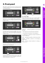
Page 17: ...elect buttons opens the Channel menu for that channel Pressing both Channel buttons at the same time opens a Channel menu for controlling the parameters of both channels at the same time 6 1 Front LED...

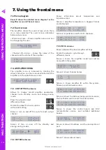
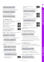
Page 18: ...off the standby and energy saving modes S t a n d b y O F F E n e r g y S a v e O F F 7 3 2 METERS submenu 7 Using the frontal menu Shows information about temperature and impedance load Screen 1 amp...

Page 19: ...splay contrast EventScreen turn on and off the event screen Screen 2 change the channel name shown on the event screen and in the Web UI N a m e E d i t o r N o S u b n e t m a s k 2 4 2 5 5 2 5 5 2 5...

Page 20: ...amplifier Note The password lock in the PASSWORD submenu is only applicable to the amplifier s menu itself and does not affect the functions of the Web UI 7 3 8 SYSTEM UNIT submenu Allows to choose m...

Page 21: ...menu Reserved for future use 7 4 6 PEQ BAND 1 6 submenus Controls the parametric equalizer of the selected channel O F F P e a k G n 1 0 F q 1 0 0 0 Q u 1 5 On Off Turn the PEQ band on or off Peak Low...

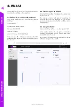
Page 22: ...eries amplifier before attempting the connection to the Web UI 8 2 Connecting to the Web UI Enter the TDC amplifier IP address in the address bar of your browser The pop up window will appear requesti...

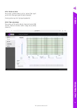
Page 23: ...source window allows one to choose the input and control the input gain for both channels It also gives access to the signal generator 8 3 2 Channel windows Two windows for each output channel provide...

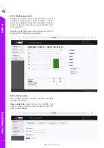
Page 24: ...and status messages channel protect channel mute signal on input indicator and sleep indicator Standby mode and energy saving mode can also be switched from the Monitoring window 8 3 4 Config window...

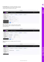
Page 25: ...address network submask and gateway IP It is also possible to switch between static IP and dynamic IP mode Misc config tab allows changing the MAC address and to set the custom username and password t...

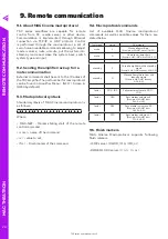
Page 26: ...ows M A G N E T c o m v f m Where MAG NET Marker stating start of the remote control command com name of the command v value to set fm Finish marker of the command 9 5 Finish markers MAG Cinema Macrop...

Page 27: ...om defects in material components and factory workmanship under the normal use and maintenance for the time as specified below All warranty repairs and maintenance of MAG Cinema products shall be carr...

Page 28: ...2 Merezhna str Bila Tserkva Kyiv region 09100 Ukraine Tel Fax 38 044 2774789 e mail info mag theatron com www mag theatron com THEATRON...

Reviews: