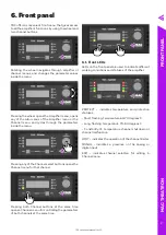
TDC series user manual rev 1.0
18
M
A
G
T
H
E
A
TR
O
N
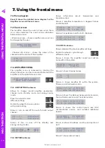
7.1. Menu diagram
Panel E shows the detailed menu diagram for the
Amplifier menu and Channel menu.
7.2. Event screen
The amplifier shows the event screen when there
is no menu selected. The event screen alternates
between two views:
- Welcome screen - shows amplifier name, and can
be changed by the user.
M A G - T H E A T R O N
T D C 3 2 0 0
- Channel info screen - shows the name of the
channels and the status of the amplifier.
C h 1 — L
C h 2 — R
7.3. AMPLIFIER MENU
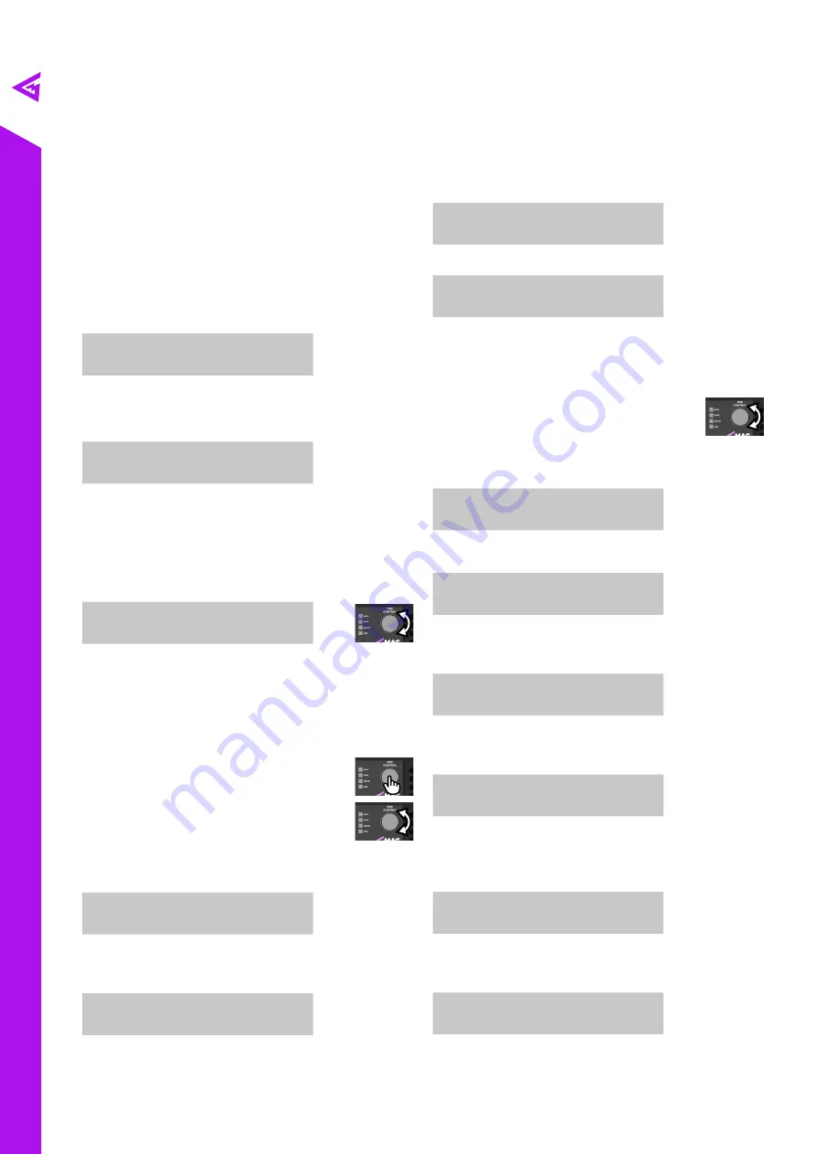
The amplifier menu is accessed by rotating the
wheel once when no other menu is selected and the
amplifier is in the splash screen mode.
« A M P L I F I E R M E N U »
A M P S E T T I N G S
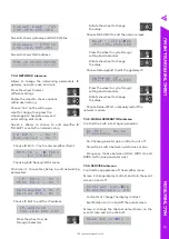
7.3.1. AMP SETTINGS submenu
Allows to change overall amplifier parameters:
channel mute, standby mode, and energy saving
mode.
Press the wheel to select
different settings.
Rotate the wheel to choose options
within each setting.
Screen 1: turn on and off the mute for each output
channel.
C h . _ 1 —
U n M u t e d
C h . _ 2 —
U n M u t e d
Screen 2: turn on and off the standby and
energy-saving modes.
S t a n d b y
█
—
O F F
E n e r g y S a v e — O F F
7.3.2. METERS submenu
7. Using the frontal menu
Shows information about temperature and
impedance load.
Screen 1: amplifier temperature in degrees Celsius
and Fahrenheit.
T e m p . M 1 :
4 9 °
T e m p . M 1 : 1 2 0 . 2 F
Screen 2: impedance loads for both channels.
I M P . 1 c h — I n f
O h m
I M P . 2 c h — I n f
O h m
7.3.3. INFO submenu
Shows detailed info about amplifier settings.
Rotate the wheel to cycle through
different screens
Screen 1: shows the amplifier model and custom
name within the system.
M O D E L — T D C 1 2 0 0
U n i t —
E m p t y
Screen 2: shows channel names.
C h 1
— L
C h 2
— R
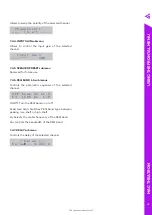
Screen 3: shows amplifier ID within the system,
firmware, and hardware version.
A m p l i f i e r _ I D : 0 0 0
F i r m H a r d : 0 0 4 : 0 1 1
Screen 4: shows the data exchange protocol version,
the bootloader version, and the serial number.
P . v : 0 0 1 B o o t : 0 1 8
S / N — 0 1 2 3 4 5 6 7 8 9 A B
Screen 5: shows the control board and DSP
microcontroller version, and installed additional
boards.
H 2 3 0 8 0 1
F 2 0 0 8 2 5
E x t . m o d . — — — : — — —
Screen 6: shows IP address and the macroprotocol
port.
I P _ a d d r ° P : 0 8 2 3 3
1 9 2 . 1 6 8 . 0 0 0 . 0 0 7
Screen 7: shows subnet mask.
US
ING T
H
E F
R
O
N
TA
L M
E
NU


