©
Install_CelmerSL100P - All specification and suggested dimension is for reference only- subject to change without further notice.
9
Manual Operation
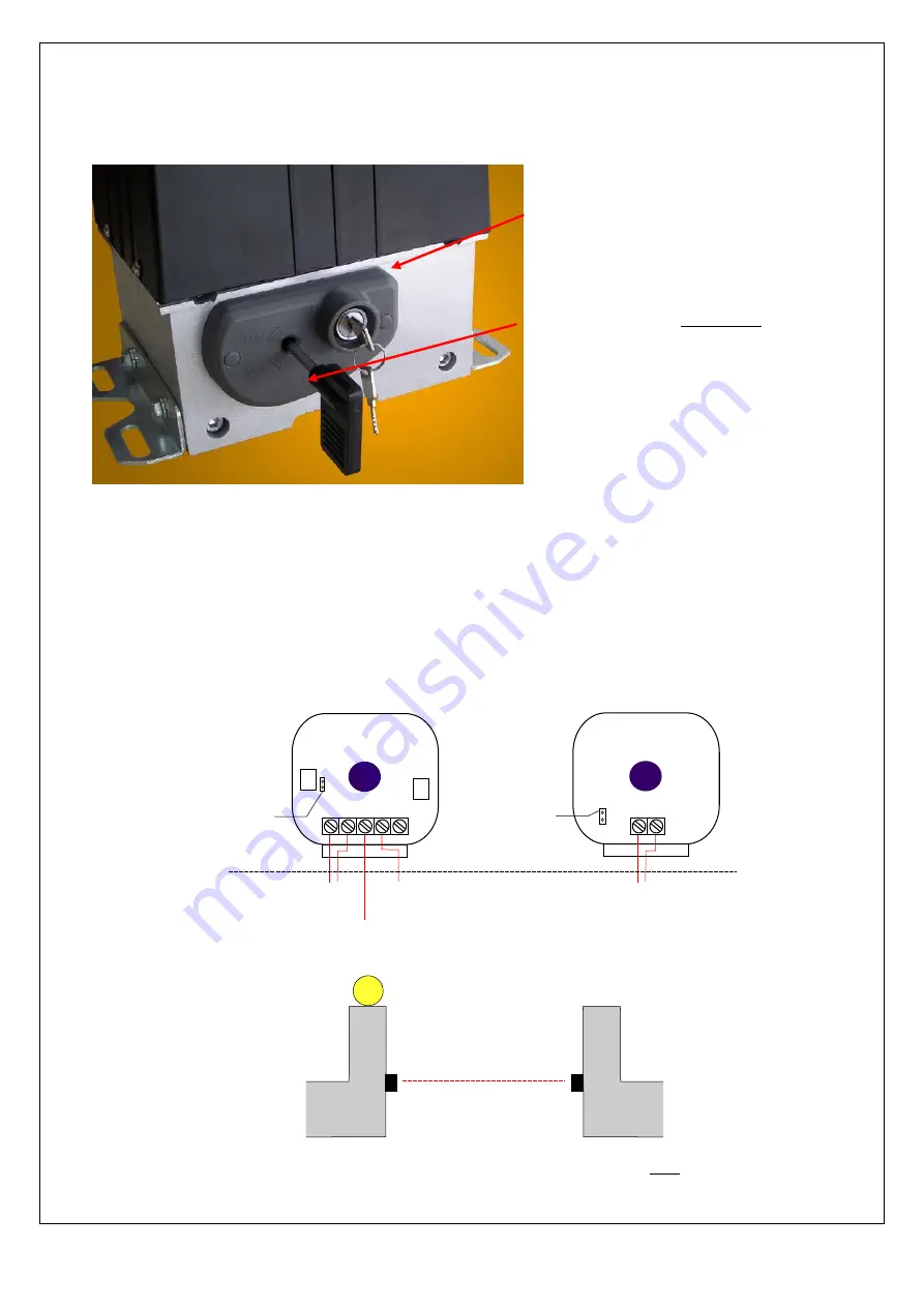
Should the need arise to operate the gate manually because of power failure or malfunction, release the clutch so that
the motor are free to rotate. This can be done with the following procedure:
CAUTION:
DO NOT turn the Alan key all the way to the end – this will cause the clutch to be completely
disengage from the gear system and unable to be tighten back later. Turn the Alan key only 2 round or less
will be able to free the clutch for manual sliding. The clutch needs to be tighten back for the automatic gate
system to resume operation.
Optional installation of photo beam
The approved photo beam to be used together with SL100P system is ART104 from DEA (Italy). Photo beam is to be
installed on the wall pillar facing each other aligning to an horizontal axis. The corresponding jumper wire on F1 board
needs to be cut to enable photo beam function. The following is the detailed wiring of the photo beam:
NO
-
C NC
+
AC24V - shared power
supply with remote
control receiver.
Common CM
share with limit switch
PIB input
F1 control panel
Power selection
No jumper - AC24V
With jumper - DC12V
-
+
AC24V - shared power
supply with remote
control receiver.
Power selection
No jumper - AC24V
With jumper - DC12V
Transmitter (TX)
Receiver (RX)
IR beam passing horizontal across
the gate entrance. Trigger signal
will be sent to control board once
IR beam is blocked by obstacle.
pillar wall
© COPYRIGHT 20 Feb 2012. All diagrams are for illustration only and does not necessary reflect the actual exact assembly/installation. This
documentation served as a reference only. It is subject to change without further notice. All the diagrams and information in this documentation
may not be duplicated or modified in any form without the written approval from
MAG®
.
1)
Use the key supplied to unlock the
clutch
2)
Turn the Alan key TWO round anti-
clockwise to release the clutch


