16
Reference & Installation Manual
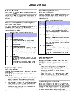
Intellizone Delay Timer
Section [065]: 010 to 255 seconds; Default = 48 seconds
Enter the desired 3-digit value into section [065] to program
the Intellizone Delay Timer.
Delay Before Alarm Report Code Transmission
Sections [001] to [016]: Zones 1 to 16; option [7]
Option [7] OFF =Delay alarm transmission disabled (default)
Option [7] ON =Delay alarm transmission enabled
This feature is commonly used with Entry Delay zones to reduce
false alarms created by new users who may not disarm the
system in time. This feature works as follows:
•
When an alarm condition occurs on a zone with this option
enabled, the console enables the bell/siren output, but does
not report the alarm to the central station until the end of the
Alarm Before Transmission Delay.
•
During this period, disarming the system disables the bell/
siren output and cancels the report code transmission.
Alarm Transmission Delay
Section [075]: 001 to 255 seconds; 000 = Disabled; Default = 0
seconds
Enter the desired 3-digit delay value into section [075] to
program the Alarm Transmission Delay.
Remote Panic Disarm Lock Delay
Section [078]: 001 to 255 seconds; 000 = Disabled; Default = 20
seconds
When a panic alarm is generated through the use of a remote
control, the system cannot be disarmed by remote control during
the Remote Panic Disarm Lock Delay.
Enter the desired 3-digit delay value into section [078] to
program the Remote Panic Disarm Lock Delay.
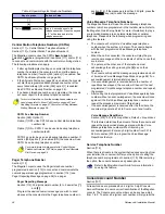
Force Zones
Sections [001] to [016]: Zones 1 to 16; Option [8]
Option [8] OFF =Force zone disabled
Option [8] ON =Selected zone is Force enabled (default)
Any open Force zones at the time of arming will be considered
deactivated by the console. If during this period a deactivated
zone is closed, the console will revert that zone to active status.
Consequently, the console will generate an alarm if the zone is
breached.
Fire zones cannot be programmed with the Force Zone
option because the console will not bypass a Fire zone when
the system is being Force armed.
Stay Delay Zones
Section [094]: Options [1]
Option [1] OFF =Stay Delay zone disabled (default)
Option [1] ON =Stay Delay zone enabled
When a Stay Delay zone is armed using the Stay or Instant
arming methods and the zone is triggered, an alarm will not
generate until the programmed Stay Delay elapses. A zone
defined as Stay Delay 1 follows the Entry Delay 1 Timer of its
assigned partition. Likewise, a zone defined as Stay Delay 2
follows the Entry Delay 2 Timer of its assigned partition. To
program the Entry Delay Timers, refer to Entry Delay 1 and Entry
Delay 2 on page 13.
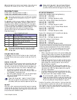
Zones 15 and 16 become Hardwire Zones
Section [095]: Options [1] and [2]
Option [1] OFF = Wireless zone 15 remains unchanged (default)
Option [1] ON =
Wireless zone 15 uses the on-board hardwire
zone input 1
Option [2] OFF = Wireless zone 16 remains unchanged (default)
Option [2] ON =
Wireless zone 16 uses the on-board hardwire
zone input 2
The Magellan console comes with two on-board zone inputs,
hardwire zone inputs 1 and 2. Section [095] options [1] and [2]
allow you to convert zones 15 and 16 from wireless to hardwire
by allowing you to connect hardwire detection devices (i.e. door
contact) to zone inputs 1 and 2.
•
With section [095] option [1] ON, zone 15 is connected to
zone input 1.
•
With section [095] option [2] ON, zone 16 is connected to
zone input 2.
EOL (End-Of-Line) Zones
Section [095]: Option [3]
Option [3] OFF = Hardwire zones 1 & 2 do not require EOL
resistors (default)
Option [3] ON =
Hardwire zones 1 & 2 require EOL resistors
This feature only applies to Magellan’s on-board zone
inputs. Section [095] options [1] and/or [2] (see Zones 15
and 16 become Hardwire Zones on page 16) must be ON in
order to use this feature.
If the hardwire detection devices connected to Magellan’s zone
inputs 1 and 2 have input terminals that require 1K
9
end of line
resistors, enable (ON) section [095] option [3]. For details on
using EOL resistors, refer to page 8.
Summary of Contents for MG-6060
Page 1: ...All In One Wireless Security System V1 0 Model MG 6060 Reference and Installation Manual...
Page 2: ......
Page 44: ...42 Reference Installation Manual...
Page 46: ......
Page 47: ......


