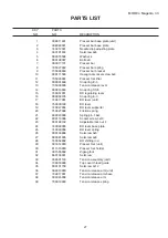
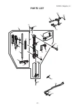
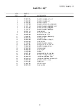
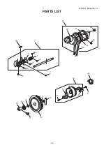
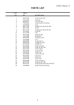
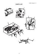
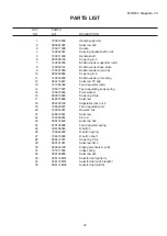
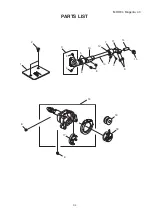
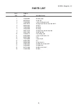
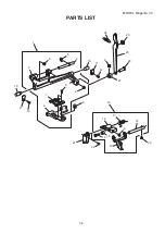
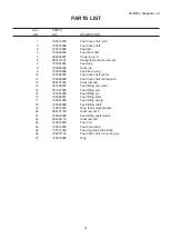
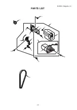
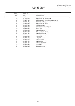
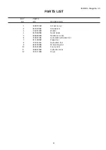
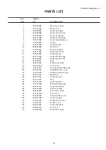
background image

33

PARTS LIST

                         KEY                  PARTS
                          NO.                  NO. 

 DESCRIPTION

MODEL: Magenta  43

1

2

3

4

5

6

7

8

9

10

11

12

13

14

15

16

17

18

19

20

21

22

23

24

25

26

27

28

29

30

31

32

33

34

35

Handle supporter

Setscrew 4x8

Handle

Carrying handle shaft (unit)

Handle shaft

Snap ring E-3

Bobbin winder supporter (unit)

Bobbin winder base plate

Bobbin winder arm (unit)

Snap ring E-6

Bobbin winder arm spring

Setscrew TP 4x8

Feed regulator (unit)

Feed regulating body spring

Plain washer

Snap ring CS-6

Setscrew

Adjustable lock nut 4

Feed regulating rod

Reverse link

Setscrew

SS rod

Setscrew 5x8

Feed regulator spring

R button

R button spring

R button shaft

Snap ring CS-4

Setscrew 5x10

Zigzag mechanism (unit)

Index spring

Setscrew 3x5

Selector dial (pattern)

Selector dial (stitch length) 

Selector dial (width)

740010008

000081005

735017308

740624001

740011009

000002105

740602209

740003101

735501005

000002806

740042009

000115607

311604302

735077007

735073003

000013800

648010009

000160102

739020007

730045001

648012001

734039004

000172602

670100006

306106004

739063002

736015000

000014007

000101301

306603109

737011009

000103808

306114M01

306118M01

306114M02

Summary of Contents for 43

Page 1: ...SERVICE MANUAL PARTS LIST MODEL Magenta 43 First Edition 08 July 2020...

Page 2: ...NEEDLE DROP 11 CLEARANCE BETWEEN NEEDLE AND SHUTTLE RACE ADJUSTMENT METHOD NO 1 12 CLEARANCE BETWEEN NEEDLE AND SHUTTLE RACE ADJUSTMENT METHOD NO 2 13 FEED DOG HEIGHT 14 NEEDLE BAR HEIGHT 15 NEEDLE TI...

Page 3: ...bar See mechanical adjustment P 15 height Needle bar height 7 Inappropriate needle to hook See mechanical adjustment P 16 timing Needle timing to shuttle 8 Inappropriate needle to See mechanical adjus...

Page 4: ...Too much thread is around on Adjust the position of stopper the bobbin 3 Lint is stuck inside the hook Clean the hook race race 4 Thread quality is too low Change to a high quality sewing thread 5 Th...

Page 5: ...ent P 21 Motor belt tension 4 Upper shaft gear is loose Eliminate the looseness 5 Not enough oil Oil all moving parts 7 Deformation of 1 Inappropriate zigzag See mechanical adjustment P 10 pattern syn...

Page 6: ...4 A TO REMOVE 1 Remove the face cover by removing the setscrew A TO ATTACH 2 Follow the above procedure in reverse SERVICE ACCESS 1 FACE COVER...

Page 7: ...1 Remove the face cover see page 4 2 Remove the dials 3 Loosen the setscrew A B and C and then remove the front cover by removing the setscrews D E F G H I and J Note Unhook the tab K from the rear co...

Page 8: ...ver and front cover see pages 4 to 5 2 Loosen the setscrews A B and C and remove setscrews D E and F 3 Pull up the spool pins Remove the machine socket Remove the rear cover clearing the presser foot...

Page 9: ...sion dial at 3 make sure the foot should be lowered If the tension is out of the standard range adjust it as follows ADJUSTMENT PROCEDURE 1 Remove the front cover see page 5 2 Turn the adjusting screw...

Page 10: ...bobbin thread tension should be 32 to 38 grams force when pulling the thread in the direction of B If the tension is out of the range adjust it as follows ADJUSTMENT PROCEDURE 1 Turn the adjusting sc...

Page 11: ...the face plate set plate 2 Raise the presser foot lever and loosen the hexagonal socket screw C on the presser bar holder Adjust the distance between the presser foot D and the needle plate E to 6 0 m...

Page 12: ...ctor dial with the maximum zigzag width and remove the front cover see page 5 2 Loosen the hexagonal socket screws 2 pcs 3 Adjust the needle swing by turning the handwheel while holding the worm so as...

Page 13: ...hole on the needle plate and the needle drop positions should be equal If not adjust as follows ADJUSTMENT PROCEDURE 1 Remove the face cover see page 4 2 Set the pattern selector dial at the maximum...

Page 14: ...move the needle bar supporter to direction A If clearance is too narrow move the needle bar supporter to direction B 4 Tighten the hexagonal socket screw NOTE After this adjustment check that the cle...

Page 15: ...tween the needle and the shuttle race in the range of 0 05 to 0 10 mm 5 Set the pattern select dial at turn the handwheel to check if the clearance between the needle and inner edges of the shuttle ra...

Page 16: ...the needle plate should be 0 75 to 0 90 mm If it is not in the range adjust as follows ADJUSTMENT PROCEDURE 1 Open the shuttle cover 2 Lower the presser foot and turn the handwheel toward you until th...

Page 17: ...the handwheel toward you until the tip of the shuttle hook meets the left side of the needle 6 Loosen the hexagonal socket screw 7 The distance between the top of the needle eye and the tip of the sh...

Page 18: ...p of the shuttle hook meets the left side of the needle 6 Loosen the hexagonal socket screws 2 pcs 7 While holding the shuttle hook so it doesn t turn turn the handwheel toward you until the needle co...

Page 19: ...ch density The range of 9 to 12 stitches in the right side row backward feeding against 10 stitches in the left side row forward feeding is considered acceptable ADJUSTMENT PROCEDURE 1 Check the stitc...

Page 20: ...d backward feeding during stretch stitch patterns make an adjustment as follows ADJUSTMENT PROCEDURE 1 Remove the cap 2 Set the pattern selector dial at and the stitch length dial at S S 3 Turn the st...

Page 21: ...g with the automatic buttonhole foot Adjusted as follows ADJUSTMENT PROCEDURE 1 Attach the buttonhole foot R 2 Pull down the BH lever Turn the adjusting screw D until the BH lever knob slightly touche...

Page 22: ...rn selector cam 4 Loosen the setscrew 5 Push the convex part of the cam follower releasing arm in the direction of arrow until the cam follower releasing arm touches position A of the pattern select c...

Page 23: ...e tension is too loose it can cause the belt to jump 2 The correct motor belt tension is when the deflection of motor belt is about 7 to 9 mm when pushing the motor belt by finger with a 300 grams for...

Page 24: ...cover WIRING 1 Remove the rear cover see page 6 2 Remove the setscrews A B and machine socket cover 3 Follow the above procedure in reverse Motor cord Cord from printed circuit board C LED Motor cord...

Page 25: ...23 PARTS LIST...

Page 26: ...24 MODEL Magenta 43 PARTS LIST 1 2 3 4 7 7 5 6 8 9 10 11 12 9 14 15 16 13 37 37 36 35 34 33 28 29 30 31 32 17 16 12 13 26 27 12 20 19 23 22 21 13 12 13 25 24 18 12 Page 10 No 12...

Page 27: ...r unit Rear cover Spool pin hole Spool pin no hole Spool pin spring Setscrew 3x10 B Spool pin spring base Spring Setscrew 4x6 Nut 4 3 7 Bed cover plate Setscrew TP 4x6 Setscrew 4x8 Setscrew 4x12 B Set...

Page 28: ...26 MODEL Magenta 43 PARTS LIST 1 2 3 4 5 6 7 8 9 10 11 12 13 14 15 16 27 27 36 38 37 39 16 34 33 26 35 29 30 31 32 17 18 21 19 23 22 24 16 20 28 26 25...

Page 29: ...Setscrew 4x6 Washer 4 Bolt 4x8 Presser bar Presser bar spring Presser bar bracket Hexagonal socket screw 4x8 Presser foot lifter Snap ring E 5 Tension release lever Snap ring CS 5 BH regulating lever...

Page 30: ...28 MODEL Magenta 43 PARTS LIST 27 28 26 23 21 24 25 1 4 7 6 22 3 2 5 8 14 15 9 10 11 12 13 16 21 20 17 18 19...

Page 31: ...x8 Needle threader plate unit Setscrew 3x5 Needle threader set plate Hexagonal socket screw 3x4 Needle bar supporter pin Spring washer Snap ring E 4 Needle Hexagonal socket screw 5x5 Needle bar suppor...

Page 32: ...30 MODEL Magenta 43 PARTS LIST 10 1 8 7 8 6 6 5 3 4 2 9 14 15 15 13 16 17 18 19 20 21 22 12 11 30 23 24 25 26 29 28 27...

Page 33: ...ring E 8 Handwheel unit Handwheel Balance weight Setscrew 3x10 B Clutch spring Setscrew 4x8 Clutch cap Crank rod unit Feed cam Crank rod Crank cam Crank cam plate Setscrew 3x12 B Hexagonal socket scre...

Page 34: ...32 MODEL Magenta 43 PARTS LIST 13 6 19 17 18 22 21 24 20 6 23 14 15 16 30 31 32 2 33 34 35 28 27 25 26 29 2 12 2 7 9 8 11 10 3 5 6 1 2 6 4...

Page 35: ...Setscrew Adjustable lock nut 4 Feed regulating rod Reverse link Setscrew SS rod Setscrew 5x8 Feed regulator spring R button R button spring R button shaft Snap ring CS 4 Setscrew 5x10 Zigzag mechanis...

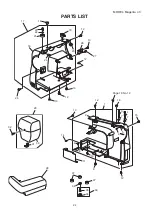
Page 36: ...34 MODEL Magenta 43 PARTS LIST 1 2 3 4 4 6 5 10 8 13 7 4 9 8 14 15 12 11 16 8 8 17 18 19...

Page 37: ...04 000172602 735061101 639036003 822070003 735236006 639037004 000001609 735610101 532096007 647515006 102261000 Needle plate Setscrew Lower shaft gear unit Hexagonal socket screw 5x5 WP Washer Bushin...

Page 38: ...36 MODEL Magenta 43 PARTS LIST 1 2 6 5 4 10 11 12 3 7 8 6 9 10 11 12 24 25 23 26 27 6 13 21 22 15 16 14 17 19 18 20 6...

Page 39: ...ng arm unit Feed lifting arm Feed lifting pin Feed lifting roller Feed lifting spring Feed lifting shaft Drop feed selecting plate Setscrew 4x12 Feed lifting shaft holder Setscrew 4x6 Feed rod Feed ro...

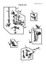
Page 40: ...38 MODEL Magenta 43 PARTS LIST 1 2 3 4 5 6 7 8 9 18 11 12 13 14 15 17 16 14 10 8...

Page 41: ...11029008 508143005 508515105 000103509 000101404 000115504 000053008 650166008 Machine sokcet whole unit Motor assembly unit including bracket Motor with pully Machine socket unit Insulating paper Pri...

Page 42: ...40 MODEL Magenta 43 PARTS LIST 1 2 3 4 5 6 7 8 9 10 11 12...

Page 43: ...6870198 647803004 102261000 647808009 639804000 740801004 611406002 737801015 620404008 045501005 306801648 741811000 Accessory set Screwdriver Bobbin Seam ripper Needle set unit Automatic buttonhole...

Reviews: