ENGLISH - 11
1.
OWNER’S MANUAL: Before powering up the
equipment, read all safety and operating instructions
and follow them as instructed. Retain the safety and
operating instructions for future reference.
2.
ATTACHMENTS: Use only those attachments
recommended by the unit manufacturer, as others may
cause hazards.
3.
ACCESSORIES: Do not place the unit on an
unstable cart, stand, tripod, bracket, or table. The unit
may fall, causing injury to a person or damage to the
unit. Mount the unit according to the manufacturer’s
instructions with the suggested mounting accessory.
4.
WATER AND MOISTURE: Do not use the unit
near water (for example, near a swimming pool, bath
tub, wash bowl, kitchen sink, or laundry tub) or in a
damp environment (like a basement or outside in the
rain).
5.
WALL OR CEILING MOUNTING: Mount the unit
to a wall or ceiling only in the manner recommended
by the manufacturer.
6.
OBJECT AND LIQUID ENTRY: Do not push
objects of any kind into the unit through openings as
they could touch dangerous voltage points and
short-out parts, possibly resulting in a fire or electric
shock. Avoid spilling liquid of any kind on the unit. If
water or any metal object (such as a paper clip, coin,
or staple) accidentally falls inside the unit, disconnect
it from the AC power source immediately and contact
Margules Audio for further instructions.
7.
HEAT: Position the unit away from heat sourc-
es such as radiators, heat registers, stoves, or other
units (including amplifiers) that produce heat.
8.
VENTILATION: Slots and openings in the
cabinet create ventilation to protect the component
from overheating. Allow at least 6 inches (16cm) of
clearance above the unit and an opening behind the
unit for airflow. Do not place the unit on a bed, sofa,
rug, built-in bookcase, or rack without adequate
ventilation.
9.
GROUNDING OR POLARIZATION: As a safety
feature, the unit may be equipped with a polarized
alternating current line plug in which one blade is
wider than the other. This plug will fit into the power
outlet only one way. If you cannot insert the plug fully
into the outlet, try reversing the plug. If the plug still
will not fit, contact a licensed electrician to update
your obsolete outlet. Do not defeat the safety purpose
of the polarized plug.
10.
POWER SOURCES: Operate the unit only from
the power source indicated on the marking label. If
you are unsure of the type of power supplied to your
home, consult your unit dealer or local power compa-
ny.
11.
POWER CORD PROTECTION: Arrange power
supply cords so that they do not suffer from foot
traffic or pinching by items placed on or against them.
Pay close attention to cords where plug enter the AC
outlet and where they exit from the unit.
12.
LIGHTNING: For added protection during a
lightning storm or when the component is idle for long
periods of time, unplug the unit from the wall outlet
and disconnect the antenna or cable system. This will
help protect the unit from lightning and power line
surge damage.
13.
POWER LINES: Do not locate an outside
antenna system in the vicinity of overhead power lines
or other electric light or power circuits. When install-
ing an outside antenna system, take extreme care to
avoid touching the power lines or circuits; contact
with them could be fatal.
14.
OVERLOADING: Do not overload wall outlets,
extension cords, or integral convenience receptacles
as this increases the risk of fire or electric shock
15.
REPLACEMENT PARTS: When replacement
parts are required, be sure the service technician has
used replacement parts specified by the manufacturer
or those having the same characteristics as the
original parts. Unauthorized substitutions may result
in fire, electric shock or other hazards.
16.
SAFETY CHECK: Upon completion of any
service or repairs to the unit, ask the service techni-
cian to perform safety checks to ensure the unit is in
proper operating condition.
17.
IMPORTANT SAFETY NOTE: Before connecting
a new product such as the U280-SC to your audio or
home theater system, turn off all other equipment
(preferably unplugging them from the AC power
source). Many audio components feature automatic
turn-on circuits that may activate during an installa-
tion, potentially causing damage to electronic compo-
nents and/or speakers. This type of damage is not
covered by product warranties, and Margules Audio
specifically disclaims responsibility for any such
damage.
•
Power Cord: The removable power cord
provided with your player was specifically designed
for use with this product, but other AC cords may be
used. Consult your dealer for advice on AC power
cords and high quality wire in your system.
•
AC Fuse: The fuse is located inside
the chassis and is not user serviceable. If
the unit does not power up, contact an
authorized service representative.
•
Wiring: Cables running inside walls should
have the appropriate markings to indicate compliance
and listing by the UL, CSA or other standards required
by the UL, CSA, NEC or your local building code.
Questions about cables inside of walls should be
referred to a qualified custom installer, a licensed
electrician, or low-voltage contractor.
18.
RECORDING COPYRIGHT: Recording of
copyrighted material for other than personal use is
illegal without permission of the copyright holder.
19.
NOTE TO CATV SYSTEM INSTALLER: This
reminder is provided to call the CATV system install-
er's attention to article 820-40 of the NEC, ANSI/NFPA
70, which provides guidelines for proper grounding
and, in particular, specifies that the cable ground shall
be connected to the grounding system of the building
as close to the point of cable entry as practical.
20. FCC INFORMATION FOR USER:
•
CAUTION: A n y c h a n g e s o r
modifications not expressly approved
by Margules Audio could void the user's
authority to operate the equipment.
•
These limits are designed to provide reason-
able protection against harmful interference in a
residential installation. This equipment generates and
can radiate radio frequency energy, and if not installed
and used in accordance with the instructions it may
cause harmful interference to radio communications.
However, there is no guarantee that interference will
not occur in a particular installation. If this equipment
does cause harmful interference to radio or television
reception, which can be determined by turning the
equipment off and on, the user is encouraged to try to
correct the interference by one or more of the follow-
ing measures:
•
Reorient or relocate the receiving antenna.
•
Increase the separation between the equip-
ment and receiver.
Connect the equipment into an outlet on a circuit
different from where the receiver is connected.
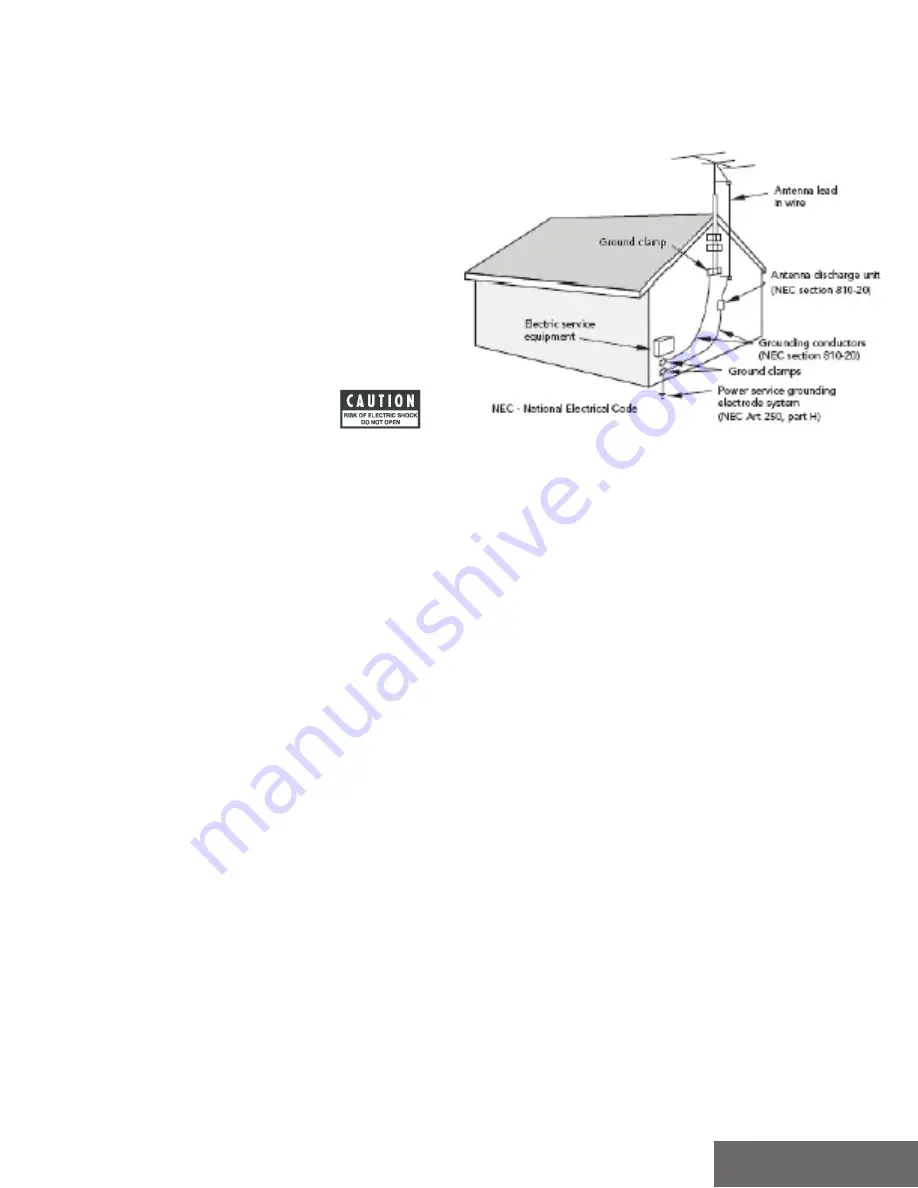
21. OUTDOOR ANTENNA INSTALLATION/SAFE
ANTENNA AND CABLE CONNECTION:
•
If an outside antenna or cable system is
connected to the equipment, be sure the antenna or
cable system is grounded in order to provide protec-
tion against built-up static charges and voltage
surges. Article 810 of the National Electrical Code,
ANSI/NFPA 70 (in Canada, Part 1 of the Canadian
Electrical Code) provides information regarding proper
grounding of the mast and supporting structure,
grounding of the lead-in wire to an antenna discharge
unit, size of grounding conductors, location of anten-
na discharge unit, connection to grounding electrodes
and requirements for the grounding electrode.
•
Outside antenna system should be located well
away from power lines, electric light or power circuits
and where it will never come into contact with these
power sources if it should happen to fall. When install-
ing an outside antenna, extreme care should be taken
to avoid touching power lines, circuits or other power
sources as this could be fatal. Because of the hazards
involved, antenna installation should be left to a
professional.
Summary of Contents for Margules ACRH-3
Page 10: ...ESPAÑOL 9 NOTAS DE INSTALACIÓN ...
Page 18: ...ENGLISH 17 INSTALL NOTES ...


