background image

19 


APPENDIX F: Pollable Serial Mode  

17 

Appendix E. Pollable Serial Mode 


The SAP pollable serial daisychainable receivers with video, audio and RS232 serial 
feature the ability to open a bi-directional session between a pollable transmitter and a 
single pollable receiver in a daisychain installation.  


Each pollable receiver must have a unique address set first. Once this has been done, 
a special command (discussed below) is sent to the transmitter to specify the receiver 
to open a session with. Once this has been done, serial communication can occur 
between the RS232 source and display. The transmitter is always addressed 0. 
Reference the 

SAP II, SAP Communication Protocol User Manual 

on configuration and 

usage of the SAP series products. 


If an address of 0 is sent, the RS232 commands will be broadcast to all receivers.  
 
The following details the installation and setup procedure. 


To set the receiver address requires that each internal serial audio daughterboard  in 
the receiver have a unique address set. This is done via an 8 position dipswitch. Use 
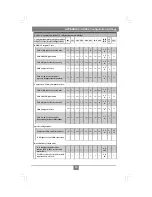
the following chart to determine the proper switch addresses. All receivers must have a 
unique address. 

It is recommended to write the address on each receiver once this step 

has been completed

. It is also recommended to keep a list of receiver addresses and 

locations to make it easier to determine which receiver/display is desired to 
communicate with. 
 
1)

Remove the top cover assembly of the receiver 

2)

Locate the 8 position dipswitch on the internal daughterboard assembly and using 
the following chart, set the receiver address. 


3)

Replace cover assembly and install unit. 

4)

Reference the 

SAP II, SAP Communication Protocol User Manual 

on configuration 

and usage of the SAP series products. 


Summary of Contents for MultiView AK500 C7

Page 1: ...MultiView AK500 C7 Receiver Quick Reference Setup Guide Magenta Research 128 Litchfield Road New Milford CT 06776 USA 860 210 0546 FAX 860 210 1758 www magenta research com...

Page 2: ...y of their respective owners FEDERAL COMMUNICATIONS COMMISSION AND INDUSTRY CANADA RADIO FREQUENCY INTERFERENCE STATEMENTS This equipment generates uses and can radiate radio frequency energy and if n...

Page 3: ...ons and Setup in General 4 3 3 2 Connections on the VGA Audio series 5 3 3 3 Connections on the SA SAP series 6 3 4 Video Adjustment 7 3 4 1 Cable Distance Compensation Settings 7 3 4 2 Skew Compensat...

Page 4: ...eo IN 75 ohms Audio models Audio IN if any 600 ohms minimum SPDIF audio models 75 Ohm Audio Characteristics Right Left summed A option SA SAP Full Stereo Line Level 600 Ohm Unbalanced Serial Character...

Page 5: ...oduct is compatible with Cat 7 FTP data cabling CatX cabling for the Magenta MultiView Series must be pinned to the TIA EIA T568B wiring specification see appendix A We also highly recommend that all...

Page 6: ...re that the CAT7 cable you intend to use has been tested to comply with the TIA EIA 568B wiring specification See Appendix A 3 3 Making the Connections 3 3 1 CONNECTIONS AND SETUP IN GENERAL This sect...

Page 7: ...ct the output CAT7 cable to the LINK OUTPUT connection 3 Apply power The LED should light and video should appear on the display make sure display is powered ON 4 To adjust video levels and skew compe...

Page 8: ...gle serial or audio signal Video modes are not affected by this Serial signals are 3 wire RS232 Tx Rx ground and have a default 9600 baud rate Full 9 pin modem signals are not supported Note when usin...

Page 9: ...ou begin ensure the EQ Adjust knob is fully counter clockwise and all skew compensation switches are in the off position Turn the EQ Adjust knob clockwise until the shadow next to the black box just d...

Page 10: ...video termination may be mismatched The transmitters and receivers ship with 75 ohm termination as the default To disable termination see Appendix B Problem Poor video quality Solution Have all recei...

Page 11: ...the MultiView CAT5 Video System XRTx Universal transmitter has been designed with full DC restoration capability This problem is easily solved via a simple switch setting in the XRTx Transmitter Pleas...

Page 12: ...annel 1 for Left audio Pin RGBHV VGA RGBS RGsB Com posite SVHS Y C YUV 1 Red Red Red C V 2 Green Green Green C Y Y 3 Blue Blue Blue U 4 5 Gnd Gnd Gnd 6 Red Red Red C V 7 Green Green Green C Y Y 8 Blue...

Page 13: ...13 11 Appendix A Cabling Pinouts Table A 3 DB9 Male Serial connector Table A 4 T568B CAT7 pinout Pin 3 wire SA Simplex 1 2 RX 3 TX TX 4 5 Ground Ground 6 7 8 9 APPENDIX A Cable Pinning...

Page 14: ...umpers on the circuit board The settings disable enable the 75 ohm termination on individual units For instance changing a transmitter termination affects the local monitor port only it doesn t affect...

Page 15: ...15 13 NOTES...

Page 16: ...time of order and will have factory configuration indicated on the top of the unit by an X in the appropriate checkbox The factory configuration may be changed or checked by using the following jumpe...

Page 17: ...out out out out All IN 2 3 2 3 Composite S Video Component Video With Left Right Line Level Audio out 1 2 out 1 2 IN IN out out All IN 1 2 1 2 With SDPIF Digital Audio out 1 2 out 1 2 IN out IN out A...

Page 18: ...units in a 19 x 1U rack Not shown are brackets for 8 units and brackets for AK series receivers and T4 transmitters The 8 Unit Rackmount Bracket holds the mounted units like the 4 Unit Rackmount Brac...

Page 19: ...RS232 commands will be broadcast to all receivers The following details the installation and setup procedure To set the receiver address requires that each internal serial audio daughterboard in the r...

Page 20: ...MAGENTA MULTIVIEW SERIES 20 18 Appendix F Pollable Serial Mode Address Chart...

Page 21: ...21 APPENDIX F Pollable Serial Mode 19 Appendix F Pollable Serial Mode Address Chart cont...

Page 22: ...MAGENTA MULTIVIEW SERIES 22 20 NOTES...

Page 23: ...23 21 NOTES...

Page 24: ...MAGENTA MULTIVIEW SERIES 24 Magenta Research 128 Litchfield Road New Milford CT 06776 USA 860 210 0546 FAX 860 210 1758 www magenta research com PN 5310242 01 Rev 01 Feb 2010...

Reviews: