© 2014 tvONE, 2791 Circleport Drive, Erlanger KY 41018 USA
Americas: 859-282-7303, EMEA: +44 (0)1843 873322, email:
tech.usa@tvone.com
www.tvone.com
Document # 5310270-01 Rev-05 (12/02/2014)
Page 1 of 2
MultiView
™II DVI-TX Transmitter:
Quick Start Guide
The
Magenta MultiView™II DVI-TX
transmitter extends a DVI-D video signal over FTP cable. There are user-configurable settings for
video, audio, and serial options which can be controlled from the front panel. For more details please refer to the complete
MultiView™
II DVI-TX User Guide
, available for download at
www.tvone.com
.
Required Tools / Hardware / Materials:
Appropriate screwdriver(s) and mounting hardware (optional, for example: rack-mount, wall
or under-desk mounting). Required materials include appropriate cables for your specific application.
Power-up Check:
After all signal and power cables are connected, then apply AC power. The power
ON
indicator should light. If the
video source is providing a valid video signal, the
video-status
indicator should also be on. If there is a local monitor attached, a video
image should appear on the monitor. If there is no image on the display, recheck all cables and ensure the display is turned on.
Front Panel Controls:
(
Refer to Figure-2) There are two buttons (
CFG
and
SEL)
, and several green LED status indicators. These are
used to control the operating modes of the transmitter, and to display current status.
In “normal-mode”, the
CFG
indicator is off. In
“configuration-mode”, the
CFG
indicator is on.
Changing Internal Settings:
In configuration-mode (
CFG indicator = on
), the
CFG
and
SEL
buttons, plus the LED indicators (1-8) will
allow you to change internal configuration settings. The changes are effective immediately and are saved in non-volatile memory.
To enter configuration-mode:
Press
CFG
button once. The
CFG
indicator
will turn on, confirming you are in configuration-
mode. Once in this mode, the LED indicators 1-8 will display the current settings as described in the tables below.
To exit configuration-mode:
Leave the buttons untouched for 10 seconds. The
CFG indicator
will turn off (normal-mode).
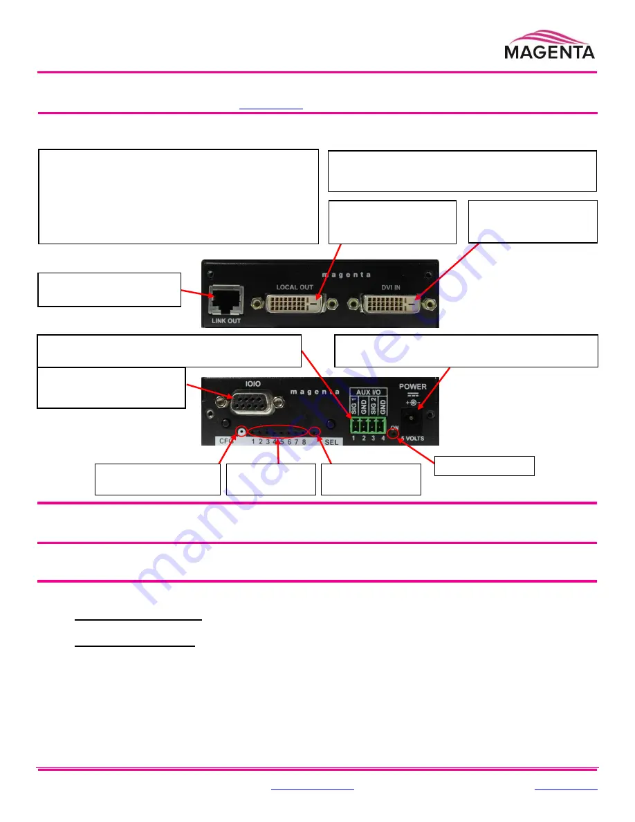
Figure 1
– MVII-DVI-TX
Transmitter Rear View
(Optional)
Depending on installation requirements
: At
any time during installation, the transmitter may be securely
mounted using appropriate brackets and hardware.
PRECAUTIONS
: (1)
Do not apply AC power until instructed to
do so.
(2)
This equipment is not intended for, nor does it
support, distribution through an Ethernet network. Do not
connect these devices to any sort of networking or
telecommunications equipment!
(3)
Use only tvONE-approved
Mul
tiView™ power adapters. Failure to do so may damage this
device and will void the warranty.
Figure 2
– MVII-DVI-TX
Transmitter Front View
Note:
The DB9 serial port is
only available when the “SAP”
option is present.
Connect the FTP cable
via the
LINK OUT
port.
(
Optional
) Connect
local display via the
LOCAL OUT
port.
Connect video source
to the transmitter’s
DVI IN
port.
(Optional
) Make your serial and/or audio connections
via the DB9
IOIO
or
AUX I/O
connectors, as needed.
Connect the DC power cable (+5VDC @ 2.6A. max) to
the
POWER
port.
Power
ON
indicator
Video-status
indicator
Operating mode:
Off
= normal,
On
= Config
Configuration
status indicators
Off
= normal,
On
= Config


