Installation
MultiView™ II T4 Installation and User Guide
9
4.3
Configuration
The T4 has a number of configurable operating parameters, and the factory-default settings will work in most
applications. However, some applications may require configuration changes. Nearly all settings are available
from the front-panel buttons/LEDs. The enclosure does not need to be opened, as there are no user-
configuration settings or jumpers inside.
4.3.1
DDC Mode Selection
The MultiView™ II T4 features the ability to send DDC/EDID display identifiers to the video source in order to
determine display capabilities. The DDC/EDID interface is a data communication channel used between plug
and play devices to accurately report a display's capabilities and identify the manufacturer. If this data is not
available, the video source may revert to a low resolution or not display at all. The T4 transmitter has three
DDC/EDID modes of operation. When the T4 is operating in “normal mode” (CFG indicator is off), it is possible to
quickly select between the three operating modes simply by using the DDC MODE button at any time:
•
STD: Selects the Magenta Magic DDC profile. Press the DDC MODE button until the STD indicator
(LED 6) is on. The Magenta Magic profile is a default set of common video resolutions. This is the
factory default setting.
•
LOCAL: Selects the DDC profile from a locally-connected display. Press the DDC MODE button
until the LOCAL indicator (LED 7) is on. The LOCAL mode allows the video source device to directly
read the DDC profile from the locally connected-display (if present). Note that LOCAL mode does not
store any DDC profile information inside the T4 device.
•
COPY: Selects a previously stored copy of a DDC profile. Press the DDC MODE button until the
COPY indicator (LED 8) is on. To use the COPY mode, a DDC profile must have already been read and
stored into the T4.
o
To perform a DDC-copy operation: Ensure the COPY mode is selected (LED 8=on), then:
1. Connect a display to the LOCAL OUT port.
2. Push and hold the COPY button until the copy-status indicator flashes 3 times, indicating a
successful operation. If it only flashes once, the operation failed and the previously stored
DDC profile (if any) will remain unchanged.
3. If desired, disconnect the display from the LOCAL OUT port.
4.3.2
General Configuration Settings
For all other configuration settings, the T4 must be in CONFIG mode (CFG indicator is on). Once in CONFIG
mode, any changes are effective immediately and are saved in non-volatile memory.
•
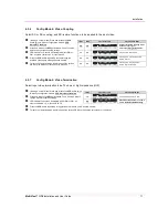
To enter configuration-mode1: Press CFG button once. The CFG indicator will turn on, confirming
you are in configuration-mode 1. Once in this mode, the LED indicators 1-8 will display the current
settings as described in the tables below.
•
To enter configuration-mode2: Press CFG button twice. The CFG indicator will flash, confirming you
are in configuration-mode 2. Once in this mode, the LED indicators 1-8 will display the current settings
as described in the tables below.
•
To exit configuration-mode: Leave the buttons untouched for 10 seconds. The CFG indicator will
turn off (normal-mode).
4.3.3
Setting Factory Defaults
To quickly reset all user-configurable options back to factory-default settings (T4-A):
1. Disconnect the DC power cable (or AC power).
2. Press and hold the CFG button.
3. Connect the DC power cable (or AC power). All LEDs blink 3 times, indicating all settings are now
changed back to factory-defaults.
4. Release the CFG button.
Note: The factory default settings represent the “T4-A” version. You can easily reconfigure this device to be a
“T4-S” by using “configuration mode-1” and “4
th
-pair settings”. See below.


