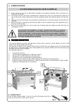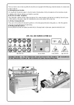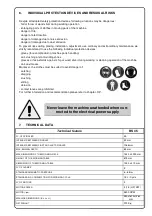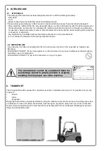
WARNING SYMBOL: ALL THE OPERATIONS HIGHLIGHTED WITH THIS SYMBOL ARE DANGEROUS
TO THE OPERATOR; PLEASE BE VERY CAREFUL IN DOING THESE OPERATIONS.
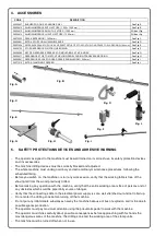
The main risk is due to moving drills. Our machine is equipped with following protection devices to reduce risks
to the minimum:
A) Emergency push button
It is inserted in the control panel, in the front side of the machine. All the movements of the machine stop im-
mediately when the emergency push button is pushed.
B) Series of stickers and plates
They describe in details all the safety instructions, the correct working procedures and identify the main parts
of the machine. One plate shows the identification and serial number of the machine.
C) Safety clamp (patented)
They are on the surface of the working table or of the already positioned working piece, so that the operator
can not put unintentionally his hands below.
D) Safety protection device
No-way-back coil preserve against accidental start. No-way-back coil preserve against accidental start
Code 36054018
Code 36054019
CEE, ISO, UNI WARNING SYMBOLS
Code 36054016
Code 36054032
Summary of Contents for BORING SYSTEM 35
Page 2: ...Page intentionally left blank...
Page 4: ...Page intentionally left blank...
Page 7: ...NOTES...
Page 38: ...Page intentionally left blank...
Page 40: ...26354000 FRAME UNIT SHEET 1...
Page 42: ...26354100 TABLE UNIT SHEET 2...
Page 44: ...26300200 RACK UNIT SHEET 3...
Page 46: ...26054300 26054301 LH RH SQUARE UNIT SHEET 4...
Page 48: ...26354401 SPINDLE HEAD UNIT SHEET 5...
Page 50: ...26300500 CLAMPING UNIT SHEET 6...
Page 52: ...26054502 CLAMP UNIT CLAMPING UNIT SUBGROUP SHEET 7...
Page 54: ...26354600 BACK STOP UNIT SHEET 8...
Page 56: ...26300700 HEAD UNIT SHEET 9...
Page 58: ...SHEET 10 26054810 1 5 1 5 Mt EXTENSION FENCE N 4 ROTARY STOPS UNIT...
Page 60: ...PNEUMATIC SYSTEM SHEET 12...
Page 65: ...Page intentionally left blank...


