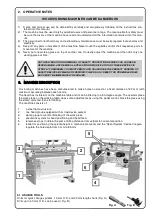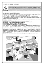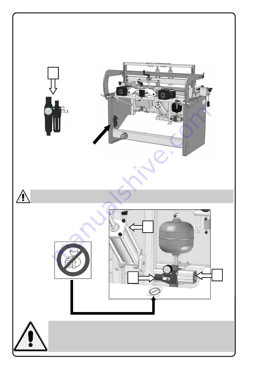
The boring machine 35 is equipped with a pressure booster (2).
This component gives a plus line pressure to the pneumatic cylinder (3) for head tipping.
The inlet pressure is set up in the factory at 5,5 Bar throught the pressure regulator (4).
14.2 PNEUMATIC CONNECTION
Connect the Filter regulator unit (1) with the air line through a rubber or nylon hose with a minimum inside
diameter of 8 mm.
If the pipe length exceeds 5/6 metres it is advisable to increase the inside diameter to 10 mm, you are also
recommended to install a supply shut-off valve on the machine with manual control complete with air relief.
The Filter purifies the air from dust and humidity protecting the valves or seals in the pneumatic cylinders.
ANY ADULTERATION OR REMOVAL OF SAFETY PROTECTION DEVICES CAN CAUSE SEVERE
DAMAGE. ANY REMOVAL, EXCLUSION OR MODIFICATION OF THESE DEVICES IS STRICTLY
FORBIDDEN. YOU MUST VERIFY AND GUARANTEE THE PERFECT RUNNING OF SAFETY DE-
VICES BY MEANS OF PERIODIC CHECKS. ANY DEFECT OR PROBABLE DRAWBACK MUST BE
IMMEDIATELY RESOLVED.
1
ATTENTION: Do not act for any reason on the pressure regulator (4) to change the pressure va-
lue. Any change of this parameter is prohibited without the written approval of the manufacturer.
4
2
3
Summary of Contents for BORING SYSTEM 35
Page 2: ...Page intentionally left blank...
Page 4: ...Page intentionally left blank...
Page 7: ...NOTES...
Page 38: ...Page intentionally left blank...
Page 40: ...26354000 FRAME UNIT SHEET 1...
Page 42: ...26354100 TABLE UNIT SHEET 2...
Page 44: ...26300200 RACK UNIT SHEET 3...
Page 46: ...26054300 26054301 LH RH SQUARE UNIT SHEET 4...
Page 48: ...26354401 SPINDLE HEAD UNIT SHEET 5...
Page 50: ...26300500 CLAMPING UNIT SHEET 6...
Page 52: ...26054502 CLAMP UNIT CLAMPING UNIT SUBGROUP SHEET 7...
Page 54: ...26354600 BACK STOP UNIT SHEET 8...
Page 56: ...26300700 HEAD UNIT SHEET 9...
Page 58: ...SHEET 10 26054810 1 5 1 5 Mt EXTENSION FENCE N 4 ROTARY STOPS UNIT...
Page 60: ...PNEUMATIC SYSTEM SHEET 12...
Page 65: ...Page intentionally left blank...


