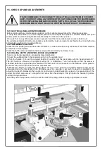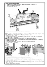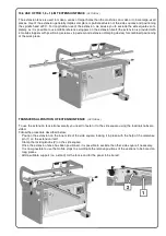
15.7 USE OF THE REFERENCE PIN FOR SETS OF HOLES ON LARGE-SIZED PIECES
( OPTIONAL )
The use of the extension fence for large-sized pieces can be complicated. Our machines are provided with a
reference pin that can be used for the repetition of a set of holes on a large-sized piece, in which the axial dis-
tance between the first drill and the last is higher than those obtainable with the boring machine used. The ref-
erence pin is aligned with the axis of the drills and it fits into a slot under the machine table when the first set of
holes has been bored. To go on boring, the reference pin can be used again by turning the knob to release the
spring that allows the reference pin to come out. The reference pin must be inserted in one of the holes that
have just been bored to allow repetition of the set of holes.
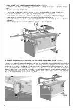
LONGITUDINAL POSITION OF THE EXTENSION FENCE
( OPTIONAL )
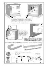
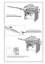
To use the extension fence longitudinally you need to fasten it to the back stop profile using the handles pro-
vided.
Follow the procedure described below:
−
Turn the side squares over to bring them out of the table, making sure they are under the work table.
−
Place the extension fence over the back stop profile as illustrated in the figure below.
−
Fasten the extension fence to the back stop profile clamping the handle (1) provided with locating pin.
−
Finally line up the extension fence to the boring line clamping the other handle (2).
−
It is now possible to use the mobile stops to co-ordinate the relative positions of the sections to be bored on
long pieces.
−
Add a suitable support (i.e. a stand) for the fence and for the panel to be bored.
2
1
Summary of Contents for BORING SYSTEM 35
Page 2: ...Page intentionally left blank...
Page 4: ...Page intentionally left blank...
Page 7: ...NOTES...
Page 38: ...Page intentionally left blank...
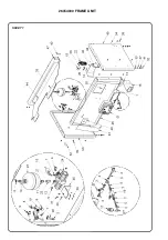
Page 40: ...26354000 FRAME UNIT SHEET 1...
Page 42: ...26354100 TABLE UNIT SHEET 2...
Page 44: ...26300200 RACK UNIT SHEET 3...
Page 46: ...26054300 26054301 LH RH SQUARE UNIT SHEET 4...
Page 48: ...26354401 SPINDLE HEAD UNIT SHEET 5...
Page 50: ...26300500 CLAMPING UNIT SHEET 6...
Page 52: ...26054502 CLAMP UNIT CLAMPING UNIT SUBGROUP SHEET 7...
Page 54: ...26354600 BACK STOP UNIT SHEET 8...
Page 56: ...26300700 HEAD UNIT SHEET 9...
Page 58: ...SHEET 10 26054810 1 5 1 5 Mt EXTENSION FENCE N 4 ROTARY STOPS UNIT...
Page 60: ...PNEUMATIC SYSTEM SHEET 12...
Page 65: ...Page intentionally left blank...

