background image


Development by 

MAGGI TECHNOLOGY S.r.l. 

Maggi Technology S.r.l   


Via delle Regioni, 299


Woodworking machinery   


50052 Certaldo ( Fi ) Italia 


Tel.  +39 0571 63541 


Fax. +39 0571 664275                             


E-mail             
 

maggi@maggi-technology.com 

Summary of Contents for BORING SYSTEM 35

Page 1: ...BORING SYSTEM 35 MACHINE CODE 16354101 201 WOODWORKING MACHINERY ORIGINAL USE AND MAINTENANCE MANUAL Always keep this manual together with the machine UK MANUAL CODE NUM 00008081 EDITION 03 2014...

Page 2: ...Page intentionally left blank...

Page 3: ...ITALY Declares that the machinery complies with all relevant provisions of the directive 2006 42 EC Machine 2004 108 EC EMC and compile the technical file of the above machinery Certaldo Issue date A...

Page 4: ...Page intentionally left blank...

Page 5: ...ictly connected with the machine configuration you have purchased The manufacturer in his pursuit of a policy of costant development and updating of the product may make any modifications without any...

Page 6: ...TH AND SPINDLE HEAD ADJUSTMENT 15 4 HORIZONTAL VERTICAL SPINDLE HEAD POSITIONING 15 5 USE OF THE REFERENCE STOP FOR STANDARD 0 90 MACHINING 15 6 USE OF THE EXTENSION FENCE 1 5 1 5 MT OPTIONAL 15 7 USE...

Page 7: ...NOTES...

Page 8: ...r use or maintenance you have always to transmit the model type and identification number contained in the plate It is absolutely forbidden to remove the plate or modify the data it contains The follo...

Page 9: ...System device ti regula regulate the hole depth from 0 mm to 85 mm 2 OPERATIVE NOTES WOODWORKING MACHINES CAN BE DANGEROUS 1 A safe and correct use can be obtained by carefully and scrupulously follo...

Page 10: ...of explosion and or fire due to possible sparks production The operator must pay maximum attention using the pneumatic pedal to work with the machine The operator must think carefully about possible c...

Page 11: ...h button is pushed B Series of stickers and plates They describe in details all the safety instructions the correct working procedures and identify the main parts of the machine One plate shows the id...

Page 12: ...PERATIONS HIGHLIGHTED WITH THIS SYMBOL ARE DANGEROUS TO THE OPERATOR PLEASE BE VERY CAREFUL IN DOING THESE OPERATIONS U S A WARNING SYMBOLS Code 36050005 Code 36050505 Code 36050506 Code 36050507 Code...

Page 13: ...hip or wood sliver during working or cleaning operation of the machine anti dust masks Moreover the clothes must be suited to avoid danger of catching dragging crushing sliding abrasion contact lenses...

Page 14: ...devices 8 2 IMPROPER USE Any operation that does not comply with the instructions given herein is to be regarded as improper use Moreover WE ADVISE YOU NOT TO lay tools against or on the machine for...

Page 15: ...easy to connect it to electrical and pneumatic power supply Put the machine in a place where there is enough lighting to see every part of the machine itself We suggest also to arrange an exhaust fan...

Page 16: ...E The Boring System boring machine is packed in a large wooden box or kit superimpo sition We strongly suggest to apply a careful and correct procedure to transport the box to the area where the borin...

Page 17: ...the two fixing devices which lock the machine to the pallet placed on the lower part of the machine frame by unscrewing the screws see figure on the left Now it is possible to separate completely the...

Page 18: ...in the figure Then assemble the clamp goup Insert the clamp unit assemble the clamp group as depicted in the figure on the left Assemble the squares of the bench on the plane After the assembling moun...

Page 19: ...ssembling steps Insert the movable stop group in the fence as depicted in the figure on the left All the assembling operations described above can be performed using the tools purchased together with...

Page 20: ...er 14 1 Pneumatic power supply see chapter 14 2 Dust suction system attention we strongly suggest to carefully follow the procedures described on chapter 14 Drilling set up procedure please carefully...

Page 21: ...ection is the one written in the plate placed on the head Black Right Red Left If the rotation direction does not match the one impressed in the plate please invert the connection cables to three phas...

Page 22: ...nstall a supply shut off valve on the machine with manual control complete with air relief The Filter purifies the air from dust and humidity protecting the valves or seals in the pneumatic cylinders...

Page 23: ...PRESSURE REGULATOR This is for regulating the compressed air operating pressure keeping it within the above mentioned limits see paragraph 14 2 14 4 WORKING CYCLE After setting the machine follow the...

Page 24: ...the spindle head 2 Turn the handle 1 to set the required height of the drills from the work table with the head turned at 0 The drill height is shown on the digital counter 2 in millimetres Turn the...

Page 25: ...e the handles 1 and 2 Use the control lever 3 and move it to the upper position to overturn the head unit Lock the handles 1 and 2 again SPINDLE HEAD POSITIONING AT AN INTERMEDIATE ANGLE OF 45 Please...

Page 26: ...is now possible to start the working cycle pressing the pneumatic pedal to start drill feed with the engine switched on make sure that the engine button is on At the same time the clamps will lock the...

Page 27: ...clamping device for combined positioning of the work piece TRANSVERSAL POSITION OF EXTENSION FENCE OPTIONAL To use the extension fence transversally you need to fasten it to the side square using the...

Page 28: ...nce pin must be inserted in one of the holes that have just been bored to allow repetition of the set of holes LONGITUDINAL POSITION OF THE EXTENSION FENCE OPTIONAL To use the extension fence longitud...

Page 29: ...at the end of the work Repeat the procedure on both sides of the triangle to obtain two mirrored frame pieces ready to be joined 15 8 USE OF THE TRIANGLE FOR 45 FRAMES OPTIONAL The 45 triangle is par...

Page 30: ...RAME MATING EXAMPLE AT 0 AND AT 45 SIMULTANEOUS MIRROR DRILLING EXAMPLES PANEL MATING EXAMPLES 16 WORKING EXAMPLES Mating parts at 0 Mating parts between 0 and 90 Assembling parts Simultaneous mirror...

Page 31: ...ltaneously transverse holes on side panels for the insertion of support panels Longitudinal positioning of the 1500mm fence equipped with two reference stops to drill line holes on large panels The lo...

Page 32: ...PANELS DRILLING EXAMPLES USING FRAME FENCE Example of the use of the standard dimension fence to drill simultaneously two frames at 0 90 PHASE 1 PHASE 2 PHASE 4 PHASE 3 Example of the use of the trian...

Page 33: ...ding to three right positions of the rack see the three arrows on the right side of the figure below besides the head group has to be positioned in the 0 0 0 0 0 vertical position as depicted in the f...

Page 34: ...ied personnel only 17 MAINTENANCE 17 1 ORDINARY MAINTENANCE PROBABLE REASON ACTION A the motor does not work B the motor is out of service push the motor start push button release the emergency push b...

Page 35: ...rator place through class 1 integrative noise meter is 76 1 dB A This measure was done according to ISO3745 rules with usual working values of speed and air pressure drill ing a shaving wood PVC cover...

Page 36: ...d only against presentation of the machine number engraved into the identification plate Upon receipt of the machine carefully check that packaging is safe and not damaged Except for different agreeme...

Page 37: ...Send to Sales and technical Assistance Via delle Regioni n 299 50052 CERTALDO Fi ITALY NOTES MAGGI TECHNOLOGY srl...

Page 38: ...Page intentionally left blank...

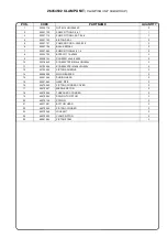
Page 39: ...6 26354401 SPINDLE HEAD UNIT SHEET 5 7 26300500 CLAMPING UNIT SHEET 6 8 26054502 CLAMP UNIT CLAMPING UNIT SUBGROUP SHEET 7 9 26354600 BACK STOP UNIT SHEET 8 10 26300700 HEAD UNIT SHEET 9 11 26054810 1...

Page 40: ...26354000 FRAME UNIT SHEET 1...

Page 41: ...ON FILTER 1 4 20 08 T P 17106B B C P 1 23 00015239 TANK 2 5 BC 1 24 00015240 PRESSURE BOOSTER 1740 50 R WITH REGULATOR 1 25 00015241 PNMX UNIDIRECTIONAL VALVE 1 4 6 07 14 1 26 00015651 FITTING T210814...

Page 42: ...26354100 TABLE UNIT SHEET 2...

Page 43: ...8364 SCREW VTCEI M10X16 UNI 5931 6 3 00018503 NUT M10 UNI 5588 6S 12 4 00018522 WASHER 10 UNI 6592 18 5 00150909 SCREW VSTEI M8X20 P C UNI 5927 6 6 36001016 BRONZE SHIMMING RING 2 7 36001127 ADJUSTMEN...

Page 44: ...26300200 RACK UNIT SHEET 3...

Page 45: ...VTBEI M8x18 2 13 00100614 SCREW VSTEI M6X20 P P UNI 5923 2 14 00150802 SCREW VSTEI M8x8 PC UNI5927 2 15 00150812 SCREW VSTEI M8x30 2 16 33201009 HANDLE M12 4 17 36000002 CYLINDER SHAFT FORK 1 18 3600...

Page 46: ...26054300 26054301 LH RH SQUARE UNIT SHEET 4...

Page 47: ...EI M6X25 UNI 5933 1 19 00018461 SCREW VTBCEI M6X25 ISO 7380 1 20 00018499 NUT M4 UNI 5588 6S 1 21 00018500 NUT M6 UNI 5588 6S 1 22 00018520 WASHER 6 UNI 6592 1 23 00018521 WASHER 8 UNI 6592 6 24 00018...

Page 48: ...26354401 SPINDLE HEAD UNIT SHEET 5...

Page 49: ...CEI M16X50 UNI 5931 2 20 00018411 SCREW VTCEI M10X120 UNI 5931 1 21 00018419 SCREW VTSPEI M4x16 1 22 00018521 WASHER 8 UNI 6592 8 23 00018522 WASHER 10 UNI 6592 1 24 00018523 WASHER 13 UNI 6592 4 25 0...

Page 50: ...26300500 CLAMPING UNIT SHEET 6...

Page 51: ...041 FISCHER SCH 8 12 GR 2 5 00018429 SCREW VTSPEI M6x20 2 6 00018500 NUT M6 UNI 5588 6S 2 7 00018501 NUT M8 UNI 5588 6S 4 8 00018503 NUT M10 UNI 5588 6S 8 9 00018602 SCREW VTBCEI M10X30 ISO 7380 8 10...

Page 52: ...26054502 CLAMP UNIT CLAMPING UNIT SUBGROUP SHEET 7...

Page 53: ...O 119 32 M6 2 9 00005103 SCREW 3 9x9 5 6955 2 10 00018439 SCREW VTSPEI M4x8 UNI 5933 2 11 00120404 SCREW VSTEI M4X4 UNI 5923 2 12 32700000 PISTON ADHESIVE 2 13 49900095 NYLON BUFFER 2 14 49901088 SLID...

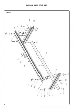
Page 54: ...26354600 BACK STOP UNIT SHEET 8...

Page 55: ...HER 8 UNI 6592 2 10 00018526 WASHER 6x18 UNI3351 2 11 00018552 NYLON CAP 4 12 00150802 SCREW VSTEI M8x8 UNI5927 3 13 36000153 THICKNESS PLATE 2 14 36001078 ALIGMENT PIN 2 15 36002065 LH BACK STOP HOLD...

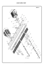
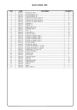
Page 56: ...26300700 HEAD UNIT SHEET 9...

Page 57: ...AL i 20 e 25 5 35 14 00018302 SCREW VTCEI M6X10 UNI 5931 12 15 00018303 SCREW VTCEI M6X20 UNI 5931 8 16 00018305 SCREW VTCEI M6X90 UNI 5931 8 17 00018316 SCREW VTCEI M8X85 UNI 5931 4 18 00018500 NUT M...

Page 58: ...SHEET 10 26054810 1 5 1 5 Mt EXTENSION FENCE N 4 ROTARY STOPS UNIT...

Page 59: ...EI 6x35 PP 4 6 00018500 NUT M6 UNI 5588 4 7 00018521 WASHER 8 UNI 6592 8 8 00018522 WASHER 10 UNI 6592 4 9 00150808 SCREW VTSTEI M8X20 8 10 36000079 THREADED PIN 4 11 36001176 FENCE SECTION BAR 1 5 Mt...

Page 60: ...PNEUMATIC SYSTEM SHEET 12...

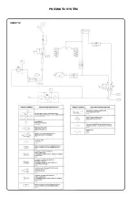
Page 61: ...0 01 1 PNMX 1 13 00015205 OVERTURNING CYLINDER 1561 80 230 01 1 PNMX 1 14 00001108 FITTING T150814 3 15 00015223 LEVER PANEL 228 32 5 PNEUMAX 1 16 00015225 PNMX FLOW CONTROL 6 01 18 1N 1 17 00001104 F...

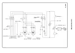
Page 62: ...URE SWITCH TRANSFORMER FUSES TRANSFORMER 0 230 400 0 24 FUSES MAIN SWITCH PROTECTION CABLE PHASE CABLES POWER SUPPLY 230V 400V 50Hz 60Hz MOTOR 3PH 230V 400V 50Hz 60Hz MOTOR SWITCH EMERGENCY MOTOR 3PH...

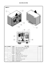
Page 63: ...MPLETE MAIN SWITCH 1 5 H1 00005075 LAMP HOLDER 1 00005076 LAMP 24V AC 2W 1 6 CABLE GLAND PG 13 5 3 7 T1 00005034 TRANSF VA30 0 230 400 415 440 0 24 1 8 F1 F2 F3 00005077 TRIPOLAR FUSE HOLDER 10X38 32A...

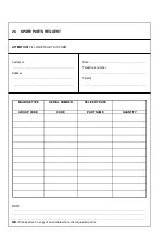
Page 64: ...NTION FILL IN DETAILS THIS FORM Customer Address Date Telephone number Telefax NOTE N B Please attach a copy of each table where the requested part is MACHINE TYPE SERIAL NUMBER DELIVERY DATE GROUP CO...

Page 65: ...Page intentionally left blank...

Page 66: ...Development by MAGGI TECHNOLOGY S r l Maggi Technology S r l Via delle Regioni 299 Woodworking machinery 50052 Certaldo Fi Italia Tel 39 0571 63541 Fax 39 0571 664275 E mail maggi maggi technology com...

Reviews: