background image

035-000049-001 

Page 4 

HCA IOM 1.1 8-28-2017 

WARNING 

CHECK the assembly and component weights to 
be sure that the rigging equipment can handle 
them safely. 
Note also, the centers of gravity and any specific 
rigging instructions. 
CHECK for adequate ventilation so that fumes 
will not migrate through ductwork to occupied 
spaces when welding or cutting inside air-
handling unit cabinet or plenum. 
WHEN STEAM CLEANING COILS be sure that 
the area is clear of personnel. 
DO NOT attempt to handle access covers and 
removable panels on outdoor units when winds 
are strong or gusting until you have sufficient help 
to control them. Make sure panels are properly 
secured while repairs are being made to a unit. 
DO NOT remove access panel fasteners or open 
access doors until fan is completely stopped. 
Pressure developed by a moving fan can cause 
excessive force against the panel which can in-
jure personnel. 
DO NOT work on dampers until their operators 
are disconnected. 
BE SURE that fans are properly grounded before 
working on them. 
Failure to follow these warnings could result in 
personal injury or equipment damage. 

DANGER 

NEVER enter an enclosed fan cabinet or reach into 
a unit while the fan is running. 
LOCK OPEN AND TAG the fan motor power dis-
connect switch before working on a fan. Take fuses 
with you and note removal on tag. Electric shock 
can cause personal injury or death. 
LOCK OPEN AND TAG the electric heat coil power 
disconnect switch before working on or near heat-
ers. 
Failure to follow these warnings could lead to per-
sonal injury or death. 

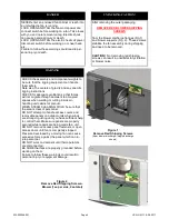
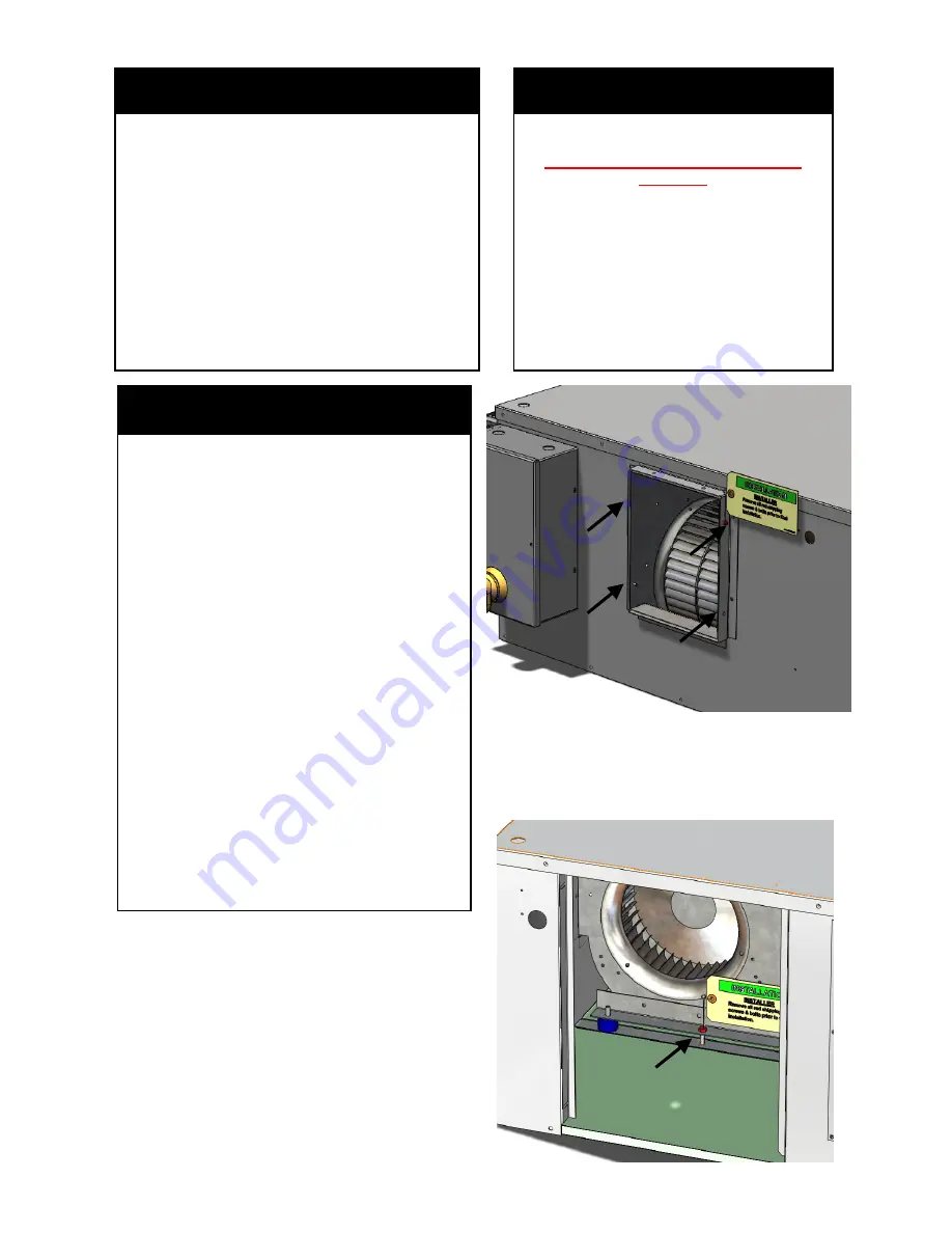
UNPACKING-CAUTION! 

After removing the outer packaging,  

REMOVE RED BLOWER SHIPPING 

SCREWS 

from the blower discharge flanges (Fig.1) 
and blower supports (Fig. 2).  These screws 
stabilize the fan assembly during shipping 
and need to be removed.    

CAUTION!  

Not removing red shipping 

screws can result in unsatisfactory vibration 
or blower noise.   

Figure 2 

Remove Red Shipping Screws– 

Blower (1ea per side, 2ea total)

Figure 1 

Remove Red Shipping Screws 

(4 per blower discharge—single discharge 

shown) 

Summary of Contents for HCA Series

Page 1: ...ARNING Hazardous voltage Discon nect and Lock Out all incoming power sources before servicing or installing unit ELECTRIC SHOCK CAN CAUSE DEATH WARNING This equipment may be in stalled well above fini...

Page 2: ...035 000049 001 Page 2 HCA IOM 1 1 8 28 2017 THIS PAGE INTENTIONALLY LEFT BLANK...

Page 3: ...G Remove Shipping Screws 4 PREINSTALLATION 5 Rigging 5 Unit Weight Calculation 5 INSTALLATION 6 18 Unit Suspension 6 7 External Vibration Isolators 7 Ductwork 8 Electrical 9 11 Service Clearance 12 Co...

Page 4: ...ampers until their operators are disconnected BE SURE that fans are properly grounded before working on them Failure to follow these warnings could result in personal injury or equipment damage DANGER...

Page 5: ...l Code IMC section 307 2 3 requires the use of auxiliary drain pans Many municipalities have adopted this code Magic Aire holds that this practice represents the standard for professional installation...

Page 6: ...ming be construct ed from structural steel or formed strut mate rials With Mixing Boxes HCA units sizes 30 40 with mixing boxes should be supported with crossbeams at each end of the unit and at the d...

Page 7: ...JURY CAUSED BY FALLING EQUIPMENT If uncertain about how to connect to the structure consult a qualified structural engineer Floor mounting Unit may be mounted on a housekeeping pad floor or platform C...

Page 8: ...side of a field provided flexible duct to the fan discharge duct collar on the front of the unit Attach the other side to the supply ductwork Seal the connec tions using duct mastic or HVAC tape Refe...

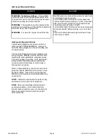
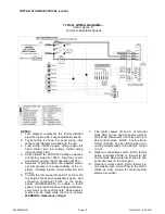
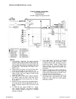
Page 9: ...WARNING For use with copper conductors only INSTALLATION ELECTRICAL INSTALLATION ELECTRICAL Typical wiring diagrams are shown on the fol lowing pages FOR REFERENCE Always re fer to the wiring diagram...

Page 10: ...circuit protection and wiring 6 To start the fan connect R and G1 or G2 or G3 to energize fan at each respective speed Add connection to terminal FLO4 on the control board EVOECM 4SPD to enable a four...

Page 11: ...components is the responsibility of the in staller including branch circuit protection and wiring 6 To start the fan apply 2 0VDC to plus and minus terminals Fan speed is variable from 2 0VDC minimum...

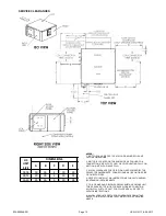
Page 12: ...S MAY BE ON ONE SIDE OR ON BOTH SIDES 4 REFER TO INSTALLATION INSTRUCTIONS FOR UNIT HANGING SUSPENSION REQUIREMENTS 5 COIL DRAINPAN OR BLOWER REPLACEMETN REQUIRES UNIT TO BE REMOVED TO FLOOR FOR SAFE...

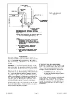
Page 13: ...vent losing seal when starting up the unit After the fan is running with the design fan inlet negative pressure the elevation of the water on the unit side of the trap will be 1 below the drain invert...

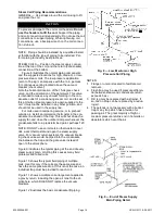
Page 14: ...nto the condensate line between the trap and the gate valve instead of open to the atmosphere Figure 9 illustrates the typical piping at the end of every steam supply main Omitting this causes many fi...

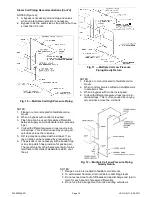
Page 15: ...with a bucket trap or any trap which has provision for passing air The great majority of high pressure return mains terminate in hot wells or deaerators which vent the air Fig 10 Multiple Coil High P...

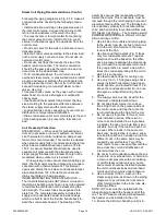
Page 16: ...s length The outer tubes are expanded into plate fins The completed assembly includes the supply and condensate header and side casings which are built to slant the fin tube bundle back to ward the co...

Page 17: ...ions The lower split of face split coils should be first on last off Fig 13 Row split coils utilize special intertwined circuits either split of these row split coils can be first on last off SUCTION...

Page 18: ...o use drop solenoid valve control as illustrated above and let the suction cutoff unloaders ride with the load The second is to use drop solenoid valve control as illustrated above with electric un lo...

Page 19: ...tachometer to confirm operating speed access doors must be closed to apply correct external static pressure to the fan 3 Check direction of rotation see Fig 15 4 Check vibration If excessive vibration...

Page 20: ...use any aggressive paint solvent cleaning agents when cleaning 5 Never use a high pressure cleaner or water spray for cleaning particularly when the fan is running WARNING Wet cleaning under volt age...

Page 21: ...prevent the formation and build up of acids There are additional precautions and control strate gies as found in various catalogues and in the ASHRAE Fundamentals Handbook when the enter ing air tempe...

Page 22: ...clear space 3 Remove the flat coil stubout panel Refer to Figure 16 and 17 Note that there is another coil access panel on the opposite side of the unit SERVICE Coil Drainpan Removal and Reinstallatio...

Page 23: ...il panel Figure 23 and 24 8 Remove coils from unit along with drainpan Drainpan will slide out of unit Figure 25 or 26 To remove coils and drainpan top will need to be lifted up as shown in Figure 21...

Page 24: ...nation up to 24 hours after sampling A low pH and high alkalinity cause system problems even when both values are within ranges shown The term pH refers to the acidity basicity or neutrality of the wa...

Page 25: ...mary Auxiliary cu in note 2 Hot Water 1 row gal Hot Water 2 row gal Coil Face Area Pre Filter 12 x 24 16 x 32 3 Not all combinations equaling 10 rows are allowed Please refer to New Magic 4 Software f...

Page 26: ...035 000049 001 Page 26 HCA IOM 1 1 8 28 2017...

Page 27: ...necessary for proper condensate drainage Is properly sized condensate trap present Is the condensate disposal system operating correctly Is auxiliary external condensate drain pan installed as recomm...

Page 28: ...035 000049 001 Page 28 HCA IOM 1 1 8 28 2017 THIS PAGE INTENTIONALLY LEFT BLANK...

Page 29: ...035 000049 001 Page 29 HCA IOM 1 1 8 28 2017 THIS PAGE INTENTIONALLY LEFT BLANK...

Page 30: ...035 000049 001 Page 30 HCA IOM 1 1 8 28 2017 HCA Series Air Handler Installation Operation and Maintenance Manual...

Reviews: