© 2006 Maytag Services
16026839
A – 7
Installation Instructions
-6-
CONNECTING THE RANGE
CONTINUED:
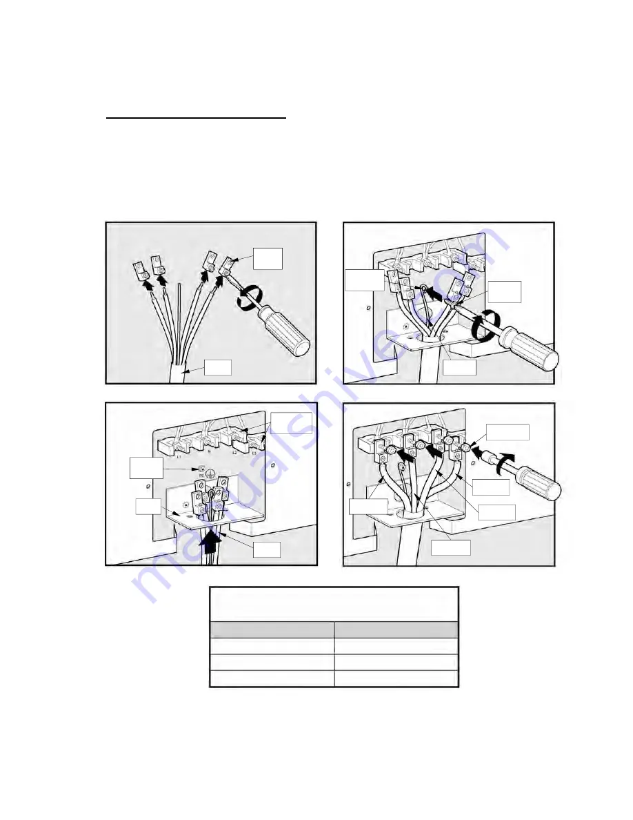
BARE WIRE CONNECTION:
For a bare wire
connection, attach the lugs (See figure 12). Use the
proper torque (See the Bare Wire Torque Chart). Pull
the service cord through (See figure 13).
The earth
wire must attach to the earth screw
(See figure 14).
Connect the remaining wires (See figure 15).
Bare Wire Torque Specifications
Lug Attached to Terminal Block—20 inch-pounds
American Wire Gage
Torque
10-14 20
inch-pounds
8 25
inch-pounds
4-6 35
inch-pounds
FIGURE 13
MAIN TERMINAL
CONNECTION
BLOCKS
PROTECTIVE
EARTH
SCREW
CONDUIT
PLATE
SERVICE
CORD
FIGURE 12
SERVICE
CORD
LUGS
SUPPLIED
IN KIT
FIGURE 14
PROTECTIVE
EARTH
SCREW
PROTECTIVE
EARTH SCREW
HOLE
PROTECTIVE
EARTH WIRE
FIGURE 15
PHASE 3 WIRE
(L3)
PHASE 2 WIRE
(L2)
PHASE 1 WIRE
(L1)
NEUTRAL WIRE
(N)
NUTS SUPPLIED
ON NUT HOLDER


