background image

15

8� 

Once the range is placed into its final location, place a carpenter’s level on the oven floor to ensure that the 
range is level from side to side and front to back�


NOTE

: The range must be level for optimal cooking and baking performance� Use a wrench to adjust the height 

of the leveling legs until the range is level from side to side and front to back�

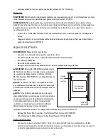
HOW TO LEVEL THE RANGE


IMPORTANT

: The range MUST BE level for optimal cooking and 

baking�
1� 

To adjust the leveling legs of the range, it must first be pulled 
forward to disengage itself from the anti-tip bracket�

2� 

Place a standard flat rack in oven�

3� 

Place the level on the rack�

4� 

Use a wrench to adjust the leveling legs up or down until the 
range is level�

5� 

Once level, push the range back into position� Check to ensure 
the rear foot is engaged in the anti-tip bracket�

Figure 15

Figure 16

HOW TO CHECK OPERATION

Electronic Burner Ignition System


NOTE

: The cooktop and oven burners use electronic igniters in place of standing pilots�

• 

Cooktop Ignition: When the cooktop control knob is turned to the “Lite” position, the system creates a 
spark to light the burner� The sparking continues, as long as the control knob is turned to “Lite”�

• 

Oven Ignition: When the oven control is turned to the desired setting, sparking will occur and ignites the gas�

Standard Surface Burners

Push in and turn the control knob to the “Lite” position� The flame should light within 4 seconds� The first time a 
burner is lit, may take longer than 4 seconds to light due to air in gas lines� Try each burner in succession until all 
burners have been checked�
What to do if burners do not light properly:
1� 

Turn all burner control knobs to the “Off” position�

2� 

Check to see that the range is plugged in� Also check that the circuit breaks has not tripped or the house 
fuse has not blown�

3� 

Check the gas shut-off valves are set to the open position�

4� 

Check the burner caps are properly positioned on each burner base�


NOTE

: If the burner continues not to light then contact your dealer or authorized service company for assistance�

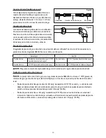
How to Adjust Flame Height

Adjust the height of top burner flames� 
The cooktop “Low” burner fame should 
be a steady blue flame approximately 
1/4” (0�64 cm) high�

Low Flame

High Flame

Summary of Contents for MCSRG24S

Page 1: ...1 PLEASE READ THIS MANUAL CAREFULLY BEFORE INSTALLING YOUR GAS RANGE AND KEEP IT FOR FUTURE REFERENCE Model MCSRG24S 24 Inch Freestanding Gas Range Installation Manual...

Page 2: ...as Supply Requirements 9 INSTALLATION INSTRUCTIONS 11 Removing Packaging Materials 11 How to Install Backsplash 11 How to Install Anti Tip Bracket 11 How to Connect Gas Line 12 How to Connect Electric...

Page 3: ...killed The range can tip if you apply too much force or weight on the oven door without the anti tip bracket being installed properly Do not step lean or sit on the door or drawer doing this may resul...

Page 4: ...call your gas supplier from a phone outside of the home Ex Go to a neighbor s home to call your gas supplier or fire department If the gas supplier cannot be reached call the fire department Installa...

Page 5: ...sking Tape Pipe Joint Compound resistant to LP NG 3 16 Carbide Tipped Masonry Drill Bit Concrete Ceramic Floors Non Corrosive Leak Detection Solution Parts Supplied Check that all parts are included 1...

Page 6: ...ces All openings in the wall or floor where the range is to be installed must be sealed The anti tip bracket must be installed to the floor Refer to How to Install Anti Tip Bracket section on page 12...

Page 7: ...red by not less than 1 4 0 64cm flame retardant millboard covered with not less than No 28 MSG sheet steel 0 015 0 4 mm stainless steel 0 024 0 6mm aluminum or 0 020 0 5 mm copper 30 76 2 cm minimum c...

Page 8: ...d to make the connection note This range is equipped with an electrical ignition system that will not operate if plugged into an outlet that is not properly polarized If codes permit and a separate gr...

Page 9: ...of gas that can be used If the types of gas listed do not include the type of gas available contact your local gas supplier LP Gas Conversion No Attempt shall be made to convert the appliance from the...

Page 10: ...ing note Gas supply pressure for testing regulator must be at least 1 WCP Water Column Pressure above the manifold pressure shown of the model serial rating plate Line pressure testing above 0 5 psi g...

Page 11: ...ly grasp the range and gently lay it on its back on the cardboard corners 5 Remove cardboard bottom note It is recommended to adjust leveling legs while the range is on its back note To place range ba...

Page 12: ...ti tip bracket to the floor Refer to Figure 11 for 3 different securing options 17 1 2 53 5cm 5 12 7cm Front Position Rear Position Diagonal Position How to Connect Gas Line warning Explosion Hazard U...

Page 13: ...ete Gas Connection 1 Open the manual shut off valve in the gas supply line The valve is open when the handle is parallel to the gas pipe 2 Test all connections by brushing on an approved noncorrosive...

Page 14: ...sis is not grounded the control panel will not operate Check with a qualified technician to ensure the metal chassis of the range is grounded properly Steps to Connect Electric Power 1 Slide Range clo...

Page 15: ...en the cooktop control knob is turned to the Lite position the system creates a spark to light the burner The sparking continues as long as the control knob is turned to Lite Oven Ignition When the ov...

Page 16: ...or each burner Control Knob Valve Stem Flathead Screwdriver Gas Conversion warning Explosion Hazard Use a new CSA International approved gas supply line Install a shut off valve Securely tighten all g...

Page 17: ...de down and re install into the regulator cap It is now positioned for use with LP Gas 5 Screw the regulator cap back into the regulator and reattach the regulator to the nipple and flare union How to...

Page 18: ...h Auxiliary Front R 0 9 NG 4 5000 0 58 LP Propane 10 5000 Semi Rapid Rear L 1 17 NG 4 6859 0 75 LP Propane 10 6859 Triple Front L 0 93 1 82 NG 4 17357 1 14 0 56 LP Propane 10 15000 Rapid Raer R 1 6 N...

Page 19: ...19 CNA International Inc d b a MC Appliance Corporation All rights reserved Magic Chef logo is a registered trademark of CNA International Inc www mcappliance com Printed in China...

Page 20: ...20...

Page 21: ...21 LEA ESTE MANUAL ANTES DE UTILIZAR SU Estufa a Gas Y GU RDELO PARA FUTURA REFERENCIA Modelo MCSRG24S Estufa a Gas Independiente de 24 Pulgadas Manual de instalaci n...

Page 22: ...7 INSTRUCCIONES DE INSTALACI N 29 Retiro de los materiales de embalaje 29 C mo instalar el protector contra salpicaduras 29 C mo instalar el soporte antivuelco 29 C mo conectar la l nea de gas 30 C mo...

Page 23: ...uede volcar la estufa y resultar muerto La estufa puede volcarse si usted aplica mucha fuerza o peso en la puerta del horno si el soporte antivuelco no ha sido instalado correctamente No se suba apoye...

Page 24: ...diatamente llame a su proveedor de gas desde un tel fono afuera de la casa Ejemplo Vaya a la casa del vecino para llamar a su proveedor de gas o al departamento de bomberos Si el proveedor de gas no p...

Page 25: ...er as resistente a PL GN Broca de alba iler a con punta de carburo de 3 16 pisos de concreto cer mica Soluci n no corrosiva para detectar fugas Piezas suministradas Verifique que todas las piezas est...

Page 26: ...rturas en la pared o piso donde la estufa se va a instalar deben ser selladas El soporte antivuelco debe ser instalado al piso Consulte la secci n C mo instalar el soporte antivuelco en la p gina 29 S...

Page 27: ...se del gabinete de madera o metal est cubierto por no menos de 1 4 0 64 cm con protector de placa cortafuego retardante de llama con l mina de acero no inferior que N 28 MSG de acero inoxidable 0 015...

Page 28: ...tar en muerte incendio o descarga el ctrica Figura 6 importante La estufa debe estar conectada a tierra el ctricamente conforme a los c digos locales y ordenanzas o en ausencia de c digos locales conf...

Page 29: ...yen personal licenciado de servicio de sistema de calefacci n personal autorizado de la compa a de gas y personal autorizado para dar servicio No seguir estas instrucciones puede resultar en muerte ex...

Page 30: ...i n m nima Presi n de una columna de agua 5 WCP presi n de columna de agua Presi n m nima 11 WCP presi n de columna de agua Presi n m xima 14 WCP presi n de columna de agua Presi n m xima 14 WCP presi...

Page 31: ...e dos o m s personas agarre firmemente la estufa y d jela caer suavemente en su parte posterior en las esquinas de cart n 5 Retire la base de cart n nota Se recomienda ajustar las patas niveladoras mi...

Page 32: ...columna de agua de 14 36 cm Ejemplos de un t cnico calificado incluyen personal licenciado de servicio de sistema de calefacci n personal autorizado de la compa a de gas y personal autorizado para da...

Page 33: ...ambos adaptadores suministrados con el juego de la l nea de gas 2 Fije un adaptador al regulador de presi n de gas y otro a la v lvula de cierre de gas y aprieta ambos C mo completar la conexi n de g...

Page 34: ...rante el ciclo normal El rendimiento de esta estufa no ser afectado si se opera en un circuito protegido GFCI Sin embargo es posible un disparo ocasional perjudicial del interruptor GFCI debido a la n...

Page 35: ...a estufa debe ser nivelada para ptima cocci n y rendimiento al hornear 1 Para ajustar las patas niveladoras de la estufa la misma debe primero ser halada hacia a delante para desengancharla del soport...

Page 36: ...te Los ajustes se deben hacer con otros dos quemadores en funcionamiento fijados a posici n de fuego medio Esto previene que la fila superior de las llamas sean ajustadas muy bajas resultando en que l...

Page 37: ...e gas propano PL nota Cuando la superficie de cocci n es convertida a gas propano PL se requiere un suministro de gas PL para proveer un m nimo de 10 a un m ximo de 14 de columna de agua al regulador...

Page 38: ...ave de tuerca de 7 mm retire los orificios de los quemadores 3 Instale los orificios adecuados en reemplazo de los que fueron retirados 4 Reinstale las bases de los quemadores los cabezales y las parr...

Page 39: ...7400 Peque o 1 29 mm 6900 Diminuto 1 10 mm 5000 Quemador superior 1 40 mm 7900 Quemador de la parte inferior 1 70 mm 10700 Tipo de gas Punto de toma de presi n GPL 10 Quemador Tama o del inyector mm C...

Page 40: ...International Inc realiza negocios bajo el nombre de MC Appliance Corporation Derechos reservados El logotipo Magic Chef es una marca registrada de CNA International Inc www mcappliance com Impreso en...

Reviews: