background image

Page 13 of 20

507389-02

Issue 1733

5.  Set the room thermostat to the desired temperature. 

If the thermostat “set” temperature is above room 

temperature after the pre-purge time expires, main 

burners will light.

To Shut Down Main Burners

1.  Turn off electrical power to unit.

2.  Move the ON/OFF switch to the “OFF” position (see 
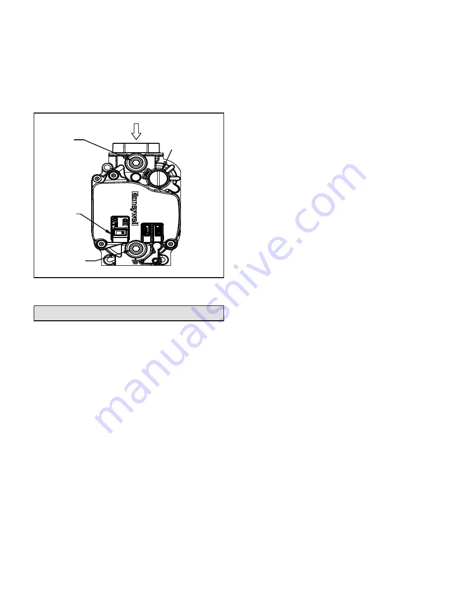
Figure 9).

Figure 9. Gas Valve

Gas Inlet

ON/OFF 

Switch

Gas Inlet 

Pressure 

Test Tap

Regulator 

Adjustment Screw 

(under cap)

Gas Manifold 

Pressure Test 

Tap

Operation

Operation of the unit is automatic and will provide heating 

and cooling depending on the setting of the thermostat.

Heating

1.  Turn on main power supply.
2.  Open manual gas shutoff valve.
3.  Set thermostat system to “HEAT”.
4.  Set thermostat to temperature desired.

Cooling

1.  Turn on main power supply.

2.  Set thermostat system switch to “COOL”.
3.  Set thermostat to temperature desired.

Heating Sequence of Operation

1.  Thermostat calls for heat.

2. 

Combustion blower starts and proper air flow is proven 

by the pressure switch closing.

3.  Blower continues to operate for 30 seconds prior to 

the burners lighting.

4. 

Ignition control begins spark and opens gas valve. The 

burners  are  lit.  Ignition  is  proved  through  the  flame 

sensor.

5.  Circulating air blower starts 30 seconds after the 

burners light.

6. 

When  the  thermostat  is  satisfied,  the  burners  and 

combustion blower shut off.

7.  Circulating air blower will shut off 120 seconds later.

If the burners should fail to ignite, the ignition control will 

try to ignite the burners a total of three times. Should the 

burners fail to ignite within the three trials for ignition, the 

ignition  control  will  lock  out  for  1  hour  before  beginning 

another ignition cycle. To reset the control, turn the 

thermostat down or off for 10 seconds and then set to 

desired setting. At this time, the ignition sequence will try 

again.

Blower Control

The blower will start approximately 30 seconds after the 

burners ignite and will stop approximately 120 seconds 

after the thermostat is satisfied. The time delay is preset at 

the factory and timing can not be adjusted.

Cooling Sequence of Operation

When the thermostat system switch is set for “COOL”, the 

blower will start 5 seconds after the thermostat calls for 

cooling and will stop 90 seconds after the thermostat is 

satisfied.

Continuous Fan Operation

Continuous operation of the air handling blower will be 

obtained if the thermostat fan switch is set to “ON”. With 

the thermostat fan switch set to “AUTO”, the air handling 

blower will cycle corresponding with the thermostat cycling.

To Shut Down Unit

For temporary or short periods of shutdown, set the 

thermostat system switch to “OFF”. For a prolonged period 

of shutdown, set the thermostat system switch to “OFF” 

and turn off the electrical power supply and the gas supply 

to the unit.

Summary of Contents for HWC9 V-Series

Page 1: ...in the vicinity of this or any other appliance Such actions could result in property damage personal injury or death WARNING Do not store combustible materials near the furnace or warm air ducts The m...

Page 2: ...r portions of the unit may be surrounded by a closet with minimum clearances to combustible material of 0 sides 2 top and 1 front and plenum Adequate clearance must be provided to install gas line uni...

Page 3: ...tion air requirements during construction The furnace heat exchanger components duct system air filters and evaporator coils must be thoroughly cleaned following final construction clean up All furnac...

Page 4: ...led in an unconditioned space the condensate drain elbow outside the unit cabinet must have heat tape suitable for PVC pipe installed and the elbow insulated This heat tape and insulation are field su...

Page 5: ...ate Drain Component Locations Side Exit Figure 4 Furnace Condensate Drain Component Locations Front Exit Condensate Trap Side Panel Upper Drain Hose from Collector Box Lower Drain Hose to drain fittin...

Page 6: ...art of the appliance The venting system must not be modified or added on to The unit contains a combustion inducer The inducer draws the combustion products out of the heat exchanger and forces them f...

Page 7: ...must be used Do not use a connector which has previously serviced another gas appliance A manual shutoff valve must be located outside the unit The use of a union located upstream of the controls is...

Page 8: ...ional Electrical Code ANSI NFPA No 70 latest edition for installations in the U S or the Canadian Electrical Code Part 1 CSA C22 1 latest edition for installations in Canada See rating plate for minim...

Page 9: ...6 deep Insert the duct into the return opening in the bottom of the unit and flange the duct over the existing flanges around the opening inside the unit Make sure that all sides of the duct are flang...

Page 10: ...615 47 590 49 565 51 TAP 2 HEAT 208 or 230 780 37 755 38 730 39 710 40 TAP 3 HEAT 208 or 230 900 32 875 33 855 34 835 34 TAP 4 COOL 208 or 230 605 575 545 520 TAP 5 COOL 208 or 230 650 615 585 555 HWC...

Page 11: ...615 N A 590 N A 565 N A TAP 2 HEAT 208 or 230 780 61 755 63 730 65 710 67 TAP 3 HEAT 208 or 230 900 53 875 54 855 55 835 57 TAP 4 COOL 208 or 230 800 775 755 735 TAP 5 COOL 208 or 230 880 860 835 815...

Page 12: ...ode A high altitude conversion kit available from the manufacturer and approved for this purpose must be used Installation and Operation in Extremely Cold Weather Areas In areas where extremely cold b...

Page 13: ...satisfied the burners and combustion blower shut off 7 Circulating air blower will shut off 120 seconds later If the burners should fail to ignite the ignition control will try to ignite the burners...

Page 14: ...ly Igniter Combustion Inducer Gas Valve Gas Manifold Rollout Switch Burner Manifold Assembly Primary Limit Heat Exchanger Access Panel Cold End Header Box Upper Drain Hose Inducer Elbow Flue Tube Drai...

Page 15: ...Page 15 of 20 507389 02 Issue 1733 Figure 11 Burner Manifold Assembly Removal Step 7 Mounting Brackets Step 8 Burner Manifold Assembly Step 9 Step 10...

Page 16: ...m the vest panel 10 Finally pull the assembly from the unit 11 Once the burner assembly is removed the burners can be cleaned using a bottle brush 12 For reassembly follow the above steps in reverse o...

Page 17: ...urner assembly 3 Remove the orifices by unscrewing them Do not use any pipe thread sealant during reassembly 4 For reassembly follow the above steps in reverse order Combustion Inducer The combustion...

Page 18: ...Heater 1 Remove the control board mounting bracket as described previously 2 Remove the furnace condensate drain and upper and lower hoses as described previously 3 Disconnect the two lead wires at th...

Page 19: ...ing chassis normally requires no maintenance since it is a closed self contained system System is charged with R410A refrigerant Periodic maintenance is limited to Cleaning the air filter Follow direc...

Page 20: ...GERANT HIGH PRESSURE SWITCH BLUE BLK WHT RED BLACK BLACK BLUE YELLOW OPERATING MODE CIRCUIT HEATING R W COOLING R G Y FAN R G ORG GREEN WHITE WHITE GREEN N G L C BLACK BLUE GREEN BLK WHT COOL HEAT UNU...

Reviews: