Page 17 of 20
507389-02
Issue 1733
2. Disconnect the orange and yellow wires at the rollout
switch.
3. Remove the screw and slip the rollout switch from
beneath the lanced tab on the burner assembly.
4. For reassembly, follow the above steps in reverse
order.
Flame Sensor
1.
Remove the control board mounting bracket as
described previously.
2.
Remove the screw and pull the flame sensor from the
bottom of burner assembly.
3. For reassembly, follow the above steps in reverse
order.
Primary Limit Switch
The primary limit will shut down the unit in case of
overheating and automatically resets when temperature
falls to an acceptable level. It is not field adjustable
1.
Remove the control board mounting bracket as
described previously.
2. Disconnect the orange and yellow wires at the primary
limit switch.
3. Remove the three screws securing the primary limit
switch to the vest panel.
4. For reassembly, follow the above steps in reverse
order.
Inducer Prover Switch
1.
Remove the control board mounting bracket as
described previously.
2. Disconnect the two purple leads at the inducer prover
switch.
3. If the tubing is in place, remove it.
4.
Remove the screw securing the switch to the bracket
and slip the strap end out of the hole in the bracket.
5. For reassembly, follow the above steps in reverse
order.
Burner Orifices
Orifices are threaded into the gas manifold. To remove
them:
1. Remove the burner & manifold assembly as described
previously.
2. Remove the four screws securing the gas manifold to
the burner assembly.
3.
Remove the orifices by unscrewing them. Do not use
any pipe thread sealant during reassembly.
4. For reassembly, follow the above steps in reverse
order.
Combustion Inducer
The combustion inducer can be removed for inspection,
replacement, or to access the heat exchanger and flue
tube extension for cleaning. To remove the combustion
inducer:
1.
Remove the control board mounting bracket as
described previously.
2. Disconnect the inducer motor leads.
3. Disconnect the inducer prover switch tubing at the
switch.
4. Disconnect the drain hose tubing at the collector box.
5.
Loosen the hose clamp at the inducer elbow-flue tube
joint (the upper hose clamp).
6. Remove the three screws securing the inducer to the
cold- end header box. Loosen clip at upper mount.
7. Pull the combustion inducer and elbow away from the
vest panel to move it free of the mounting legs on the
cold-end header box, while pulling the inducer elbow
free of the flue tube extension.
8. Pull the inducer and elbow out of the compartment.
9.
The flue tube extension can be cleaned if necessary.
Leave it in place; do not remove it from the unit.
10. If replacing the inducer with a new part, transfer
inducer orifice from old inducer. Attach inducer orifice
11. For reassembly, follow the above steps in reverse
order.
Combustion Inducer Orifice
The combustion inducer orifice meters the air flow needed
for proper combustion. Orifices are unique to each heating
input, and the correct one must always be used. The
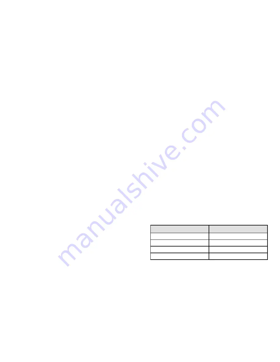
orifices are color-coded as an aid. Refer to Table 3:
Model
Orifice Color
HWC9N22
Blue
HWC9N33
Black
HWC9N44
Gray
HWC9N55
Brown
Table 3.
Refer to Figure 12 to remove the combustion inducer
orifice:


