


Page 4 of 20
507389-02
Issue 1733
Installing without a Wall Sleeve
Refer to the following directions and Figure 1 for guidance
in installing the unit without a wall sleeve:
1.
Measure the size of the unit and provide an opening
in an outside wall that will accept the unit. Local
ordinances may require a steel lintel to support the
wall above the opening. The opening must be square
in all four corners.
2. Position the unit so that the grilles on the outside face
of the unit are flush or extend beyond the face of the
exterior wall, but not recessed more than 2” from the
face of the building. Provide a support under the unit,
inside the building. Make sure that the inside support
does not block the return air. The unit should be
installed level or pitched slightly to the outside of the
building so that rain water will drain away.
3. Seal the space between the unit and building opening
using a non-hardening caulking compound. The seal
must be weather-tight to prevent entrance of moisture
and water into the building. Make sure the drain holes
in the base are not plugged with caulking.
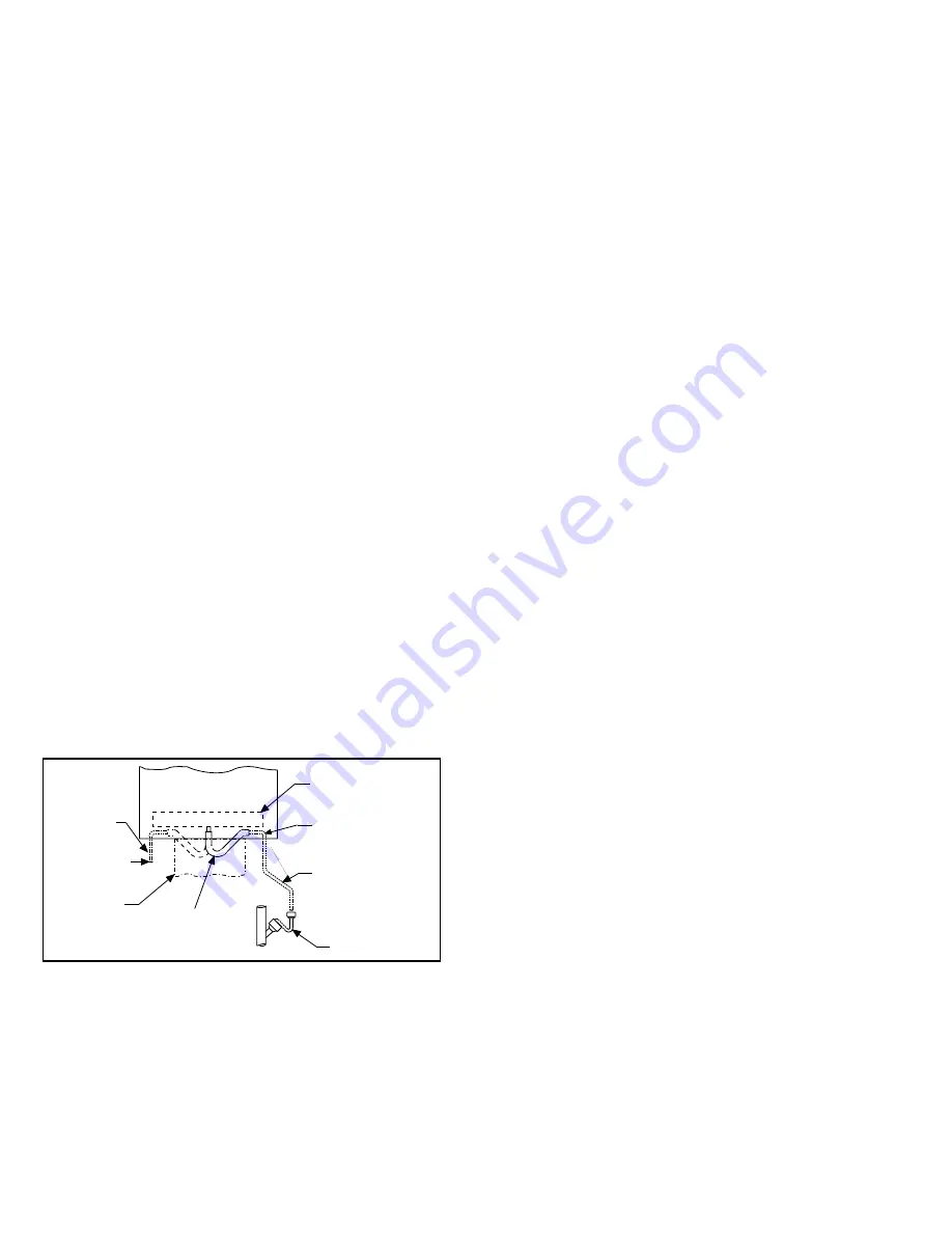
Evaporator Condensate Drain
Install the plastic drain tube (furnished) over the 5/8” O.D.
fitting in the center of the Evaporator condensate pan.
Connect other end of the drain tube to the open trap (see
Figure 2). The plastic drain connection is provided so that
it may be disconnected from the permanent drain tubing in
the building in the event it becomes necessary to remove
the cooling chassis assembly.
The drain line should pitch gradually downward at least 1”
per 10’ of horizontal run to the open drain trap.
Be certain that the plastic drain tube has free drainage and
is not crimped or flattened at any bend.
Figure 2. HWC Evaporator Condensate Drain
Installation
Drain Pan
Open Drain Trap
Return
Air Duct
To Open
Drain Trap
Alternative
Method
5/8
" I.D.
Plastic Tube
(Supplied)
Top of Drain Tube
Must be Below
Bottom of Drain Pan
Drain Tube - Pitch 1"
for every 10 ft.
(Field Supplied)
Furnace Condensate Drain
The HWC9 furnace is provided with an internal condensate
drain and drain fitting. A street elbow, a hose barb and a
spigot adapter for connection to the drain fitting are factory-
supplied in the manual bag. All other piping is field-supplied
to suit the installation and local codes.
If the furnace is installed in an unconditioned space, the
condensate drain elbow outside the unit cabinet must
have heat tape suitable for PVC pipe installed, and the
elbow insulated. This heat tape and insulation are field-
supplied from standard hardware items that are available
locally, and they must be installed in accordance with the
instructions provided by their manufacturers.
Units are shipped with the drain fitting installed for side-exit
condensate drainage. The drain fitting can be repositioned
for front-exit condensate drainage if desired. Do not
relocate or remove the internal condensate trap.
If unit will be started immediately upon completion of
installation, the drain must be primed as described in the
procedure outlined in the “Start-up” section.
Field-installed piping from the furnace must slope downward
a minimum of 1/2” per foot toward the floor drain.
Piping for Side-Exit Condensate Drain
Determine whether the installation better suits a side-exit or
a front-exit furnace condensate drain. For side condensate
drain, see Figure 3 for component locations and additional
details. A 2” clearance to the cabinet side is required for
service access to the condensate drain fitting when using
the side location.
1. Install the factory-supplied street elbow to the drain
fitting by threading into place. Use a thread sealant
suitable for PVC; do not use thread tape.
2. Use the appropriate primer and solvent cement to
bond field-supplied drain line piping or fittings to the
PVC street elbow. Do not use copper tubing or existing
copper condensate lines for drain line.
3.
Route the piping to an open floor drain. Do not connect
directly to evaporator condensate drain line.
Piping for Front-Exit Condensate Drain
For front condensate drain, see Figure 4 for component
locations and additional details. Use the factory-supplied
hose barb with field-supplied flexible tubing or spigot and
hose coupling for these installations. A 2” or 4”(depending
of choice of fittings) clearance to the cabinet front is
required for service access when using the front location.
The modifications necessary to convert to front-exit
condensate drain are:
1.
Disconnect the lower drain hose from the drain fitting.
2.
Remove the screw securing the drain fitting to the
division panel.
3.
Remove the drain fitting and rotate it so that it faces
the front of the furnace.
4. Replace the securing screw.
5. Disconnect lower drain hose from drain trap and rotate
the hose so that the angled end will connect to the
drain fitting in its new orientation.


