Page 7 of 20
507389-02
Issue 1733
8. If improper venting is observed during any of the
above tests, the common venting system must be
corrected. See National Fuel Gas Code, ANSI Z223.1
(latest edition) or CAN/CGA B149.1 & .2 Canadian
Installation Codes to correct improper operation of
common venting system.
Gas Connections
The gas line to the unit should be adequately sized to
prevent undue pressure drop and should never be smaller
than the manual valve used. Consult the local utility or
National Fuel Gas Code for complete details on special
requirements in sizing gas piping.
The units supplied for operation with natural gas contain
a gas regulator which must be operated with inlet gas
pressures specified on the rating plate. If gas line pressure
exceeds this figure, an additional high pressure regulator
must be installed to reduce this pressure.
Units for operation with propane must be converted with a
kit supplied by the manufacturer and require for operation
an inlet pressure of 11” W.C. minimum and 13” W.C.
maximum. A regulator is also required on the propane tank.
If a flexible gas connector is required or allowed by
the authority that has jurisdiction, black iron pipe shall
be installed at the gas valve and extend outside the
furnace cabinet. The flexible connector can then be
added between the black iron pipe and the gas supply
line.
CAUTION
Compounds used on threaded joints of gas piping must
be resistant to the actions of liquified petroleum gases.
IMPORTANT
Never use a flame to check for gas leaks. Explosion
causing injury or death may occur.
CAUTION
If local codes allow use of a flexible gas connector, a new
listed connector must be used. Do not use a connector
which has previously serviced another gas appliance.
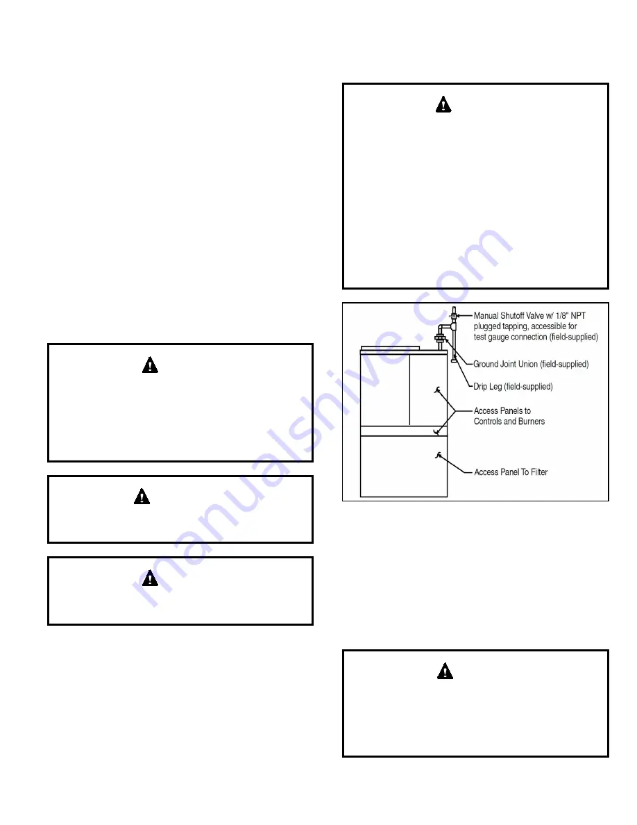
A manual shutoff valve must be located outside the unit.
The use of a union located upstream of the controls is
recommended; between the controls, and the manual
shutoff valve. This will facilitate removal of controls and
manifold. See Figure 5 for recommended placement of the
union.
Provide a drip leg in the supply piping located exterior
to the unit. Piping connections must be sealed with non-
hardening pipe joint compound resistant to propane.
The furnace must be isolated from the gas supply piping
system by closing the individual manual shutoff valve
during any pressure testing of gas supply piping system
at test pressures equal to or less than 1/2 psig or 14”
W.C. If the piping system is to be tested at pressures
in excess of 1/2 psig, the furnace and its individual
shutoff valve must be disconnected from the gas supply
piping system. The gas valve supplied with this furnace
is rated at 1/2 psig. Any higher pressure may rupture
the pressure regulator diaphragm which will cause
overfiring of the burners and improper burner operation.
This action may produce a high concentration of carbon
monoxide which can result in asphyxiation.
WARNING
Figure 5. Gas Supply Piping
Leak Check
After gas piping is completed, carefully check all piping
connections (factory and field installed) for gas leaks. Use
a leak detecting solution or other preferred means.
NOTE:
If emergency shutoff is necessary, shut off the main
manual gas valve and disconnect the main power to the
furnace. The installer should properly label these devices.
Some soaps used for leak detection are corrosive to
certain metals. Carefully rinse piping thoroughly after
leak test has been completed. Do not use matches,
candles, flame or other sources of ignition to check for
gas leaks.
CAUTION


