Page 12 of 18
508196-01
Issue 2120
Maintenance
Disconnect all electrical power to the unit before
conducting any maintenance procedures. Failure to
disconnect the power could result in personal injury or
death.
WARNING
The refrigeration system normally requires no maintenance
since it is a closed, self-contained system.
Periodic inspection and maintenance normally consists of
changing or cleaning filters and (under some conditions)
cleaning the coils.
Filter
Inspect the filter once a month. Replace disposable filter or
clean the washable filter as necessary (a minimum of three
times each heating or cooling season is recommended).
To clean the washable filter, shake filter to remove excess
dirt and/or use a vacuum cleaner. Wash filter in soap or
detergent water and replace after filter is dry.
Motors
The indoor and outdoor fan motors are permanently
lubricated and require no maintenance.
Outdoor Coil
Foreign material should not be allowed to accumulate on
the outdoor coil surface or other parts in the air circuit.
Cleaning should be as often as necessary to keep the coil
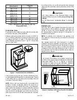
clean. To clean the coil, remove the lower access panel
and blow out debris by using compressed air or water.
Be
sure power to unit is shut off before using water to
clean the coil.
Care should be used when cleaning the coils so that
the coil fins are not damaged.
Primary and Secondary Condensate Drain
Foreign material should not be allowed to clog the drain
hole. Inspect and clear drain opening prior to each heating
and cooling season.
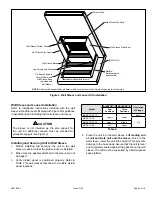
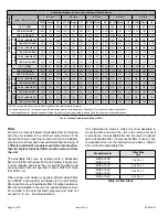
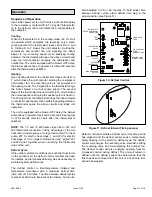
The defrost control is also equipped with a set of pins to
aid in the troubleshooting of the defrost system (see Figure
11). The following is a brief outline of the testing of the
defrost system.
1. Defrost sensor must be closed, 32°F or below. If
temperatures are such that the switch will not close,
jumper between defrost sensor terminals on the
defrost control.
2. Start system in heating operation.
3. Place the defrost pin jumper on the test pins for a brief
second, then place back on the proper defrost time
setting (30, 60, or 90). This will speed up defrost time
interval as shown in Table 7.
Defrost Control Setting
Defrost Test Cycle Time
30 minutes
7 seconds
60 minutes
14 seconds
90 minutes
21 seconds
Table 7. Defrost Test Cycle Time
The reversing valve will then shift to defrost mode and
the outdoor fan should stop. After 2 seconds of defrost
operation, the reversing valve should shift back to heating
operation and the outdoor fan should start.
Diagnostic LEDs
The state (Off, On, Flashing) of two LEDs on the defrost
board (DS1 [Red] and DS2 [Green]) indicate diagnostics
conditions that are described in Table 8.
Mode
Green LED (DS2)
Red LED (DS1)
No power to control
Off
Off
Normal operation /
power to control
Simultaneous slow flash
Timed lockout
Alternating slow flash
Low pressure switch
fault
Off
Slow flash
Low pressure switch
lockout
Off
On
High pressure switch
fault
Slow flash
Off
High pressure switch
lockout
On
Off
Table 8.


