508196-01
Issue 2120
Page 3 of 18
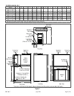
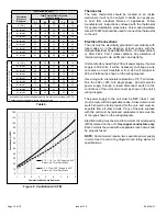
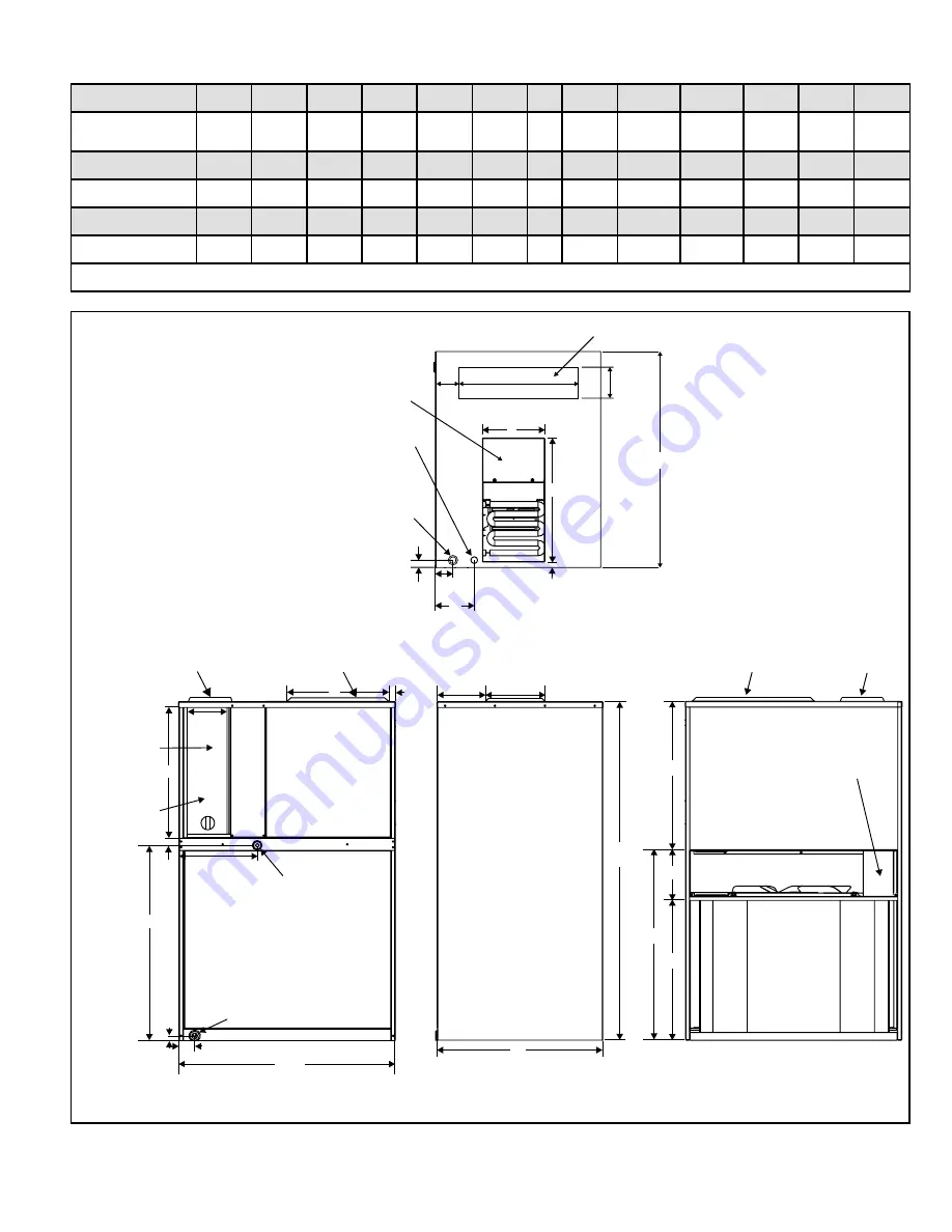
Unit Dimensions (in.)
Model
A
B*
C
D
E
F
G
H
J
K
L
M
N
*MHP4-12-091*P
*MHP4-12-121*P 43-7/8 16-7/8 25-1/4 21-1/2 18-5/8 19-1/4
6
8
16
17-1/16
3/4
2-1/4
24-5/8
*MHP4-12-181*P 47-7/8 18-7/8 27-1/4 21-1/2 20-5/8 21-1/4
6
8
16
19-1/16
3/4
2-1/4
26-5/8
*MHP4-12-241*P 55-7/8 22-7/8 31-1/4 24-3/8 24-5/8 25-1/4
6
8
16
22-7/16
3/4
1
30-5/8
*MHP4-12-301*P 55-7/8 22-7/8 31-1/4 24-3/8 24-5/8 25-1/4
6
11-3/8 10-7/16 22-7/16
3-3/4
1
30-5/8
*MHP4-14-361*P 67-7/8 26-7/8 35-1/4 24-3/8 28-5/8 29-1/4 10 11-3/8 10-7/16 22-7/16
3-3/4
1
38-5/8
* Dimension B represents the height of the optional front return air duct opening
J
Return Air
Opening
K
M
Thermostat
Wiring
Connections
Line Voltage
Knockouts
(7/8 and 1-1/8 Dia.)
Top View
3/4”
H
2-1/4”
5”
Supply Air
Opening
1”
6-1/16”
28”
H
6-1/8”
Side View
D
A
N
Outdoor Fan Discharge
Outdoor
Coil
F
G
E
Rear View
Return Air
Opening
Supply Air
Opening
Ventilation
Air Chase
Secondary Condensate
Drain Pan 3/4” NPT*
Primary Condensate
Drain Pan 3/4” NPT*
Tool-less
Filter Access
Supply Air
Opening
Indoor
Blower /
Controls
Access
Optional
Front
Return Air
Opening
Compressor / Gauge Ports /
Outdoor Fan Access
Front View
J
C
B
L
10-5/8”
5/8”
2”
28”
Return Air
Opening
7-3/4”
1”
* Provisions must be made to properly drain condensate from the primary and secondary drain pans.
Figure 1.


