506325-01
Issue 1734
Page 7 of 15
The location of fresh air capable models must conform to
the requirements of National Fire Protection Association
NFPA No. 54 in regards to proximity of forced air inlets
to flue gas terminals. Improper installation could result
in personal injury or death.
WARNING
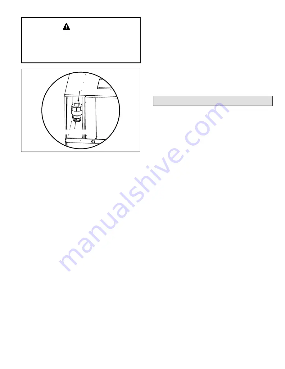
Figure 6. Fresh Air Intake Pipe and Cap
Fresh Air Intake Pipe
Threaded Cap
Thermostat
The room thermostat should be located on an inside
wall where it will not be subject to drafts, sun exposure,
or heat from electrical fixtures or appliances. Follow
manufacturer’s instructions enclosed with the thermostat
for general installation procedures. Color-coded insulated
wires (#18 AWG) should be used to connect the thermostat
to the unit.
Electrical Connections
All wiring must be done in accordance with the National
Electrical Code (NEC), ANSI/NFPA No. 70 (latest edition);
Canadian Electrical Code CSA C22.2 Part 1 (latest edition);
or local codes, where they prevail. Any alteration of internal
wiring will void certification and warranty.
Units are factory wired for a 230 volt power supply. If power
supply is 208 volts, it will be necessary to change a wire
connection on unit transformer from 240 volt terminal to
208 volt terminal as shown on the wiring diagram.
Use wiring with a temperature limitation of 75°F minimum.
Run the 208 or 230 volt, 60 hertz electric power supply
through a fused disconnect switch to the control box of the
unit and connect as shown in the wiring diagram located
on the inside of the control access panel.
The unit must be electrically grounded in accordance with
local codes or, in the absence of local codes, with the
National Electrical Code ANSI/NFPA No. 70 (latest edition)
or CSA C22.2 Part 1 (latest edition).
Operation
Sequence of Operation
Upon initial “power up” to unit, there is a 3-minute time delay
to the compressor contactor (R to Y). Any 24V interrupt (R,
C) to the defrost control will initiate the 3-minute delay to
the contactor.
Cooling
When the thermostat is in the cooling mode, the O circuit
is powered which energizes the reversing valve. Upon
cooling demand, the thermostat closes circuit R to Y and
G. Closing R to Y closes the unit contactor, starting the
compressor and outdoor fan. The thermostat automatically
closes R to G circuit which also brings on the indoor
blower at the same time. Upon satisfying cooling demand,
the thermostat will open the above circuits and open the
main contactor, stopping the compressor and outdoor
fan. The unit is equipped with a time delay; the blower will
continue to operate for 90 seconds which improves system
efficiency.
Heating
Upon heating demand, the thermostat closes circuit R to
Y, which closes the unit contactor, starting the compressor
and outdoor fan. The reversing valve is not energized in
the heating mode. The thermostat again automatically
brings on the indoor fan at the same time. The second
stage of the thermostat closes circuit R to W, which closes
the unit sequencers, bringing the auxiliary electric heat on.
Upon satisfying heating demand, the thermostat opens the
above circuits and stops unit operation.
NOTE:
The 7.2 and 10 kW heats strips offer a W1 and
W2 thermostat connection. Taking advantage of the two
heat strip circuits requires a 3-stage thermostat (Y for heat
pump, W1 for electric heat stage 1, and W2 for electric
heat stage 2). If a 2-stage thermostat is used, “pigtail” W1
and W2 wires together when connecting the thermostat
wires at the unit.
Power supply to the unit must be NEC Class 1 and must
comply with all applicable codes. A fused disconnect switch
should be field provided for the unit. The switch must be
separate from all other circuits. If any of the wire supplied
with the unit must be replaced, replacement wire must be
of the type shown on the wiring diagram. Electrical wiring
must be sized to minimum circuit ampacity marked on the
unit.
Use copper conductors only
. Each unit must be
wired with a separate branch circuit and be properly fused.
NOTE:
Some MHP4 models require two separate power
supply circuits. See the unit wiring diagrams and rating
plates for specifications.


